
Key facts
- Brand
- Analog Devices
- Model
- AD667
- Industry
- Industrial
- Documents
- 4
- Languages
- EN
- Last added
- 2012-08-02
Start here
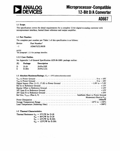
Analog Devices AD667 12-Bit D/A Converter Datasheet
The document provides a complete specification for the AD667, a 12-bit D/A converter featuring a microprocessor interface, buried Zener reference, and output amplifier. It covers part numbering, case outlines (DIP and LCC), and absolute maximum ratings including voltage limits and thermal characteristics.
Detailed electrical specifications are provided in Table 1, covering parameters such as relative accuracy, differential nonlinearity, gain error, offset errors, and power supply rejection ratio for both unipolar and bipolar configurations. The document also includes a functional block diagram, terminal assignments, microcircuit technology group information, and truth tables for latch functionality.
Analog Devices AD667 specifications
| Resolution | 12-bit |
|---|---|
| Relative Accuracy (Group 1) | +/- 4 LSB max |
| Differential Nonlinearity (Group 1) | +/- 3/4 LSB max |
| Gain Error (Group 1) | +/- 0.20 % FSR max |
| Power Dissipation | 1000mW |
| Storage Temperature Range | -65°C to +150°C |
All Analog Devices AD667 documents by type
Ratings, dimensions and ordering codes, for selection and design work.
Questions answered in these manuals
What are the available package types for the AD667?
The device is available in a 28-Pin DIP (D-28) and a 28-Pin LCC (E-28A).
What is the maximum power dissipation for the AD667?
The maximum power dissipation is rated at 1000mW.
What supply voltages does the AD667 require?
It operates from ±12 V or ±15 V power supplies.
How fast does the AD667 settle to 0.01 % of full scale?
Settling time is between 2 µs and 4 µs depending on the feedback resistor value.
What is the digital input voltage threshold?
The threshold of the digital input circuitry is set at 1.4 V and does not vary with supply voltage.
How do I adjust the zero offset for bipolar output?
Turn all bits OFF and adjust the 100 Ω trimmer R1 until the output reads –5.000 V.