
Key facts
- Brand
- Analog Devices
- Model
- ADCLK944
- Category
- Other Electronics
- Documents
- 2
- Languages
- EN
- Last added
- 2012-08-02
Start here
ANALOG DEVICES UG-125 handbook
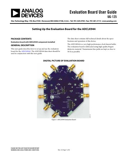
This user guide explains how to set up and use the ADCLK944 evaluation board. The board is fabricated using high-quality Rogers dielectric material, with transmission line paths kept as close to 50 Ω as possible. It is designed for the ADCLK944, a very high performance clock fanout buffer.
Read onlineAnalog Devices ADCLK944 specifications
| Operating Frequency | 7.0 GHz |
|---|---|
| Broadband Random Jitter | 50 fs rms |
| Power Supply Voltage | 2.5 V to 3.3 V |
| Output Resistance | 250 Ω |
| Maximum Output Frequency | 7.0 GHz |
| Operating Temperature Range | -40°C to +85°C |
| Package Type | 16-lead LFCSP |
Source: Analog Devices ADCLK944 Clock Fanout Buffer Datasheet
All Analog Devices ADCLK944 documents by type
Ratings, dimensions and ordering codes, for selection and design work.
Day-to-day operation, settings and troubleshooting. Start here if the product is already set up.
Questions answered in these manuals
What is the maximum output frequency of the ADCLK944?
The maximum output frequency is 7.0 GHz.
What is the broadband random jitter specification?
The broadband random jitter is 50 fs rms.
What is the recommended setup for the ADCLK944 evaluation board?
The recommended setup uses VCC set to 2.5 V to 3.3 V, VEE set to GND, and includes a single power supply, signal source, high bandwidth oscilloscope, and matched high speed cables.
What are the basic equipment requirements for the evaluation board?
The basic equipment required includes one single power supply, one signal source, one high bandwidth oscilloscope, and four matched high speed cables.