
Key facts
- Brand
- Analog Devices
- Model
- ADCLK854
- Category
- Other Electronics
- Documents
- 2
- Languages
- EN
- Last added
- 2012-08-02
Start here
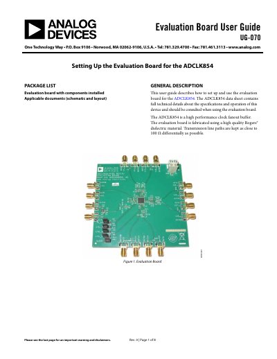
ANALOG DEVICES UG-070 handbook
This user guide provides instructions for setting up and using the ADCLK854 evaluation board. It details the recommended board setup, including power supply requirements and input configurations for differential and single-ended operation. The document also explains how to configure the programmable clock outputs using jumpers.
Read onlineAnalog Devices ADCLK854 specifications
| Product Type | High performance clock fanout buffer |
|---|---|
| Recommended Supply Voltage | 1.8 V |
| Max Differential Input Voltage (CLK1) | 0.15 V to 1.8 V |
| Max Differential Outputs | 12 |
| Max Single-Ended Outputs | 24 |
Source: ANALOG DEVICES UG-070 handbook
All Analog Devices ADCLK854 documents by type
Day-to-day operation, settings and troubleshooting. Start here if the product is already set up.
Ratings, dimensions and ordering codes, for selection and design work.
Questions answered in these manuals
What is the recommended supply voltage for the evaluation board?
The recommended setup sets the supply voltage (V S) to 1.8 V.
How are the clock outputs configured?
Outputs are configured using jumpers CTRL_A, CTRL_B, CTRL_C, and SLEEP to select between LVDS and CMOS modes.
How many selectable differential inputs does the ADCLK854 have?
It provides two selectable differential inputs.