
Key facts
- Brand
- Analog Devices
- Model
- ADCLK950
- Category
- Other Electronics
- Documents
- 2
- Languages
- EN
- Last added
- 2012-08-02
Start here
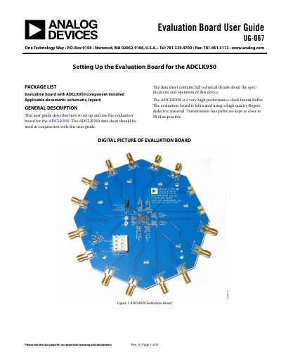
Analog Devices ADCLK950 Evaluation Board User Guide UG-067
This document is a user guide for the Analog Devices ADCLK950 Evaluation Board (UG-067). It provides instructions on setting up the board for device evaluation, detailing the required equipment such as power supplies, signal sources, and oscilloscopes. The guide explains that the ADCLK950 is a very high performance clock fanout buffer fabricated using Rogers dielectric material.
Read onlineAnalog Devices ADCLK950 specifications
| Operating Frequency | 4.8 GHz |
|---|---|
| Broadband Random Jitter | 75 fs rms |
| Supply Voltage | 3.3 V ±10 % |
| Temperature Range | –40 °C to +85 °C |
| Output Differential Swing | 1.6 V (800 mV each side) |
| Package | 40‑lead LFCSP (CP‑40‑8) |
| Maximum Output Frequency | 45‑48 GHz |
Source: Analog Devices ADCLK950 Clock Fanout Buffer Datasheet
All Analog Devices ADCLK950 documents by type
Day-to-day operation, settings and troubleshooting. Start here if the product is already set up.
Ratings, dimensions and ordering codes, for selection and design work.
Questions answered in these manuals
What is the recommended voltage setting for VCC on the evaluation board?
The recommended setup sets VCC to 3.3 V.
From: Analog Devices ADCLK950 Evaluation Board User Guide UG-067
What is the acceptable range for the peak-to-peak input voltage swing at CLK1?
The range is 0.2 V p-p to 1.7 V p-p.
From: Analog Devices ADCLK950 Evaluation Board User Guide UG-067
What is the operating frequency of the ADCLK950?
The device operates at a frequency of 4.8 GHz.
What supply voltage does the ADCLK950 require?
It requires a 3.3 V supply with a ±10 % tolerance.