
Key facts
- Brand
- Analog Devices
- Model
- AD9550
- Category
- Other Electronics
- Documents
- 2
- Languages
- EN
- Last added
- 2012-08-02
Start here
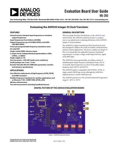
Analog Devices UG-203 AD9550 Evaluation Board User Guide
The document provides instructions for setting up power and signal connections on the AD9550 evaluation board. It details how to connect a 3.3 V CMOS reference input and measurement devices via SMA connectors.
The guide explains how to program the device using DIP switches (S1 through S4) to configure frequency translation ratios, output driver modes (LVPECL, LVDS, or CMOS), and PLL parameters based on specific pin combinations.
Analog Devices AD9550 specifications
| Input Frequency Range | 8 kHz to 200 MHz |
|---|---|
| Output Frequency | up to 810 MHz |
| Supply Voltage | 3.3 V |
| Power Consumption | <450 mW |
| Operating Temperature | -40°C to +85°C |
Source: Analog Devices UG-203 AD9550 Evaluation Board User Guide
All Analog Devices AD9550 documents by type
Day-to-day operation, settings and troubleshooting. Start here if the product is already set up.
Ratings, dimensions and ordering codes, for selection and design work.
Questions answered in these manuals
What logic families can the AD9550 outputs support?
The device supports LVPECL, LVDS, or single-ended CMOS logic levels for its two output clocks.
From: Analog Devices UG-203 AD9550 Evaluation Board User Guide
How is the AD9550 evaluation board powered?
It is powered via the TB1 connector, where Pins 2-6 connect to a 3.3 V supply and Pins 1 and 5 connect to ground.
From: Analog Devices UG-203 AD9550 Evaluation Board User Guide
What are the supported output formats?
The device supports LVPECL, LVDS, and single-ended CMOS logic levels.
What is the maximum output frequency?
The maximum output frequency is 810 MHz.