
Key facts
- Brand
- Analog Devices
- Model
- AD9523-1
- Category
- Other Electronics
- Documents
- 2
- Languages
- EN
- Last added
- 2012-08-02
Start here
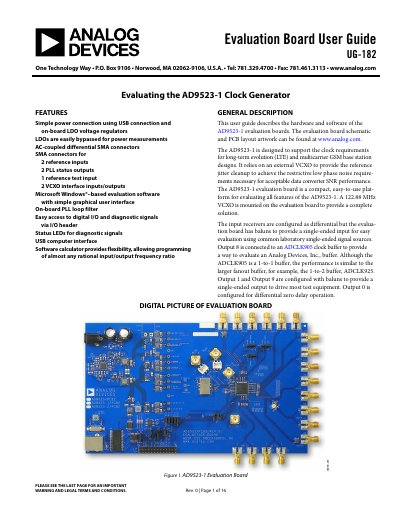
ANALOG DEVICES UG-182 handbook
This document serves as the user guide for the AD9523-1 Clock Generator evaluation board. It details the board's features, such as USB power connection, differential SMA connectors, and on-board PLL loop filters. The guide explains how to configure jumpers for SPI or I2C modes and set up power connections for power measurements.
Read onlineAnalog Devices AD9523-1 specifications
| Reference Jitter Cleanup | relies on an external VCXO |
|---|---|
| On-board VCXO Frequency | 122.88 MHz |
| Power Connection | USB connection and on-board LDO voltage regulators |
| Reference Inputs | 2 reference inputs |
| PLL Status Outputs | 2 PLL status outputs |
| Reference Test Input | 1 reference test input |
| Software Platform | Microsoft Windows-based |
Source: ANALOG DEVICES UG-182 handbook
All Analog Devices AD9523-1 documents by type
Day-to-day operation, settings and troubleshooting. Start here if the product is already set up.
Ratings, dimensions and ordering codes, for selection and design work.
Questions answered in these manuals
What is the purpose of the AD9523-1 evaluation board?
The evaluation board is designed to support the clock requirements for long-term evolution (LTE) and multicarrier GSM base station designs.
What is the default configuration for the reference inputs?
By default, the reference inputs on this evaluation board are ac-coupled and terminated with 50 Ω to ground.
What is the output frequency range of the AD9523-1?
The device can generate outputs from less than 1 MHz up to 1 GHz.
From: Analog Devices AD9523-1 Low Jitter Clock Generator Datasheet
What is the absolute output jitter at 122.88 MHz?
The absolute output jitter is less than 150 fs at 122.88 MHz.
From: Analog Devices AD9523-1 Low Jitter Clock Generator Datasheet