
Key facts
- Brand
- Analog Devices
- Model
- ADCLK948
- Category
- Other Electronics
- Documents
- 2
- Languages
- EN
- Last added
- 2012-08-02
Start here
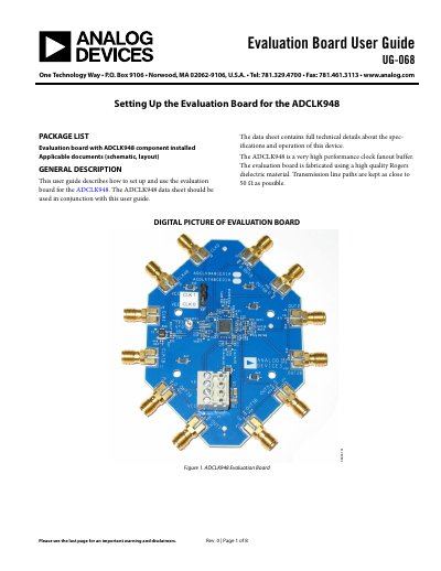
ANALOG DEVICES UG-068 handbook
This document is the User Guide (UG-068) for the Analog Devices ADCLK948 evaluation board. It details the package contents, general description of the board's high-quality Rogers dielectric construction, and the recommended hardware setup for evaluating the device. The guide specifies that the board is fabricated to keep transmission line paths as close to 50 Ω as possible.
Read onlineAnalog Devices ADCLK948 specifications
| Input voltage swing range | 0.2 V p-p to 1.7 V p-p |
|---|---|
| Power supply voltage | 3.3 V |
| Transmission line impedance | 50 Ω |
| Number of differential outputs | eight |
Source: ANALOG DEVICES UG-068 handbook
All Analog Devices ADCLK948 documents by type
Day-to-day operation, settings and troubleshooting. Start here if the product is already set up.
Ratings, dimensions and ordering codes, for selection and design work.
Questions answered in these manuals
What is the recommended power supply setup for the ADCLK948 evaluation board?
The recommended setup uses VCC set to 3.3 V and VEE set to GND.
What equipment is required to evaluate the ADCLK948?
A single power supply, a signal source, a high bandwidth oscilloscope, and matched high speed cables are required.
What is the maximum operating frequency of the ADCLK948?
The ADCLK948 can operate up to 4.8 GHz.
What is the typical broadband random jitter of the ADCLK948?
The typical broadband random jitter is 75 fs rms.