
Key facts
- Brand
- Analog Devices
- Model
- ADCLK954
- Category
- Other Electronics
- Documents
- 2
- Languages
- ZH · EN
- Last added
- 2012-08-02
Start here
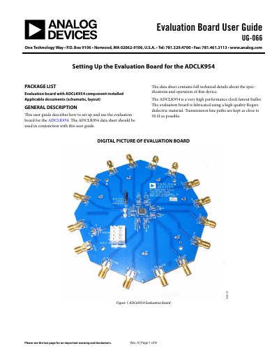
ANALOG DEVICES UG-066 handbook
The document is a user guide for the Analog Devices ADCLK954 evaluation board. It details the package contents, recommended setup procedures involving power supplies and signal sources, and explains how to connect the 12 differential clock outputs to an oscilloscope using matched coaxial cables or probes.
The guide includes diagrams of the board layout, schematic artwork showing trace layers and component placement, and specific instructions for jumper settings. It also provides a list of basic equipment required for evaluation. This manual is written in Chinese.
Analog Devices ADCLK954 specifications
| Operating Frequency | 4.8 GHz |
|---|---|
| Broadband Random Jitter | 75 fs rms |
| Supply Voltage | 3.3 V (2.97‑3.63 V) |
| Output Differential Swing | 1.6 V |
| Temperature Range | -40 °C to +85 °C |
| Package | 40‑lead LFCSP |
Source: Analog Devices ADCLK954 Clock Fanout Buffer Datasheet
All Analog Devices ADCLK954 documents by type
Day-to-day operation, settings and troubleshooting. Start here if the product is already set up.
Ratings, dimensions and ordering codes, for selection and design work.
Questions answered in these manuals
What is the ADCLK954 evaluation board used for?
This user guide describes how to set up and use the evaluation board for the ADCLK954, which is a very high performance clock fanout buffer.
What voltage settings are required for the recommended board setup?
The recommended setup requires V CC to be set to 3.3 V and V EE to be set to GND.
What is the maximum output frequency of the ADCLK954?
The device can operate up to 48 GHz output frequency.
What supply voltage does the ADCLK954 require?
It requires a 3.3 V supply, with a nominal range of 2.97 V to 3.63 V.