
Key facts
- Brand
- Analog Devices
- Model
- ADP2120
- Industry
- Industrial
- Documents
- 2
- Languages
- EN
- Last added
- 2012-08-03
Start here
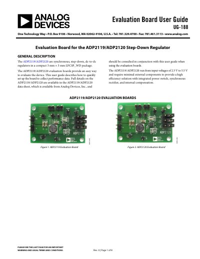
Analog Devices ADP2119/ADP2120 Evaluation Board User Guide UG-188
The document provides a user guide (UG-188) for the ADP2119/ADP2120 Evaluation Boards, which are designed to evaluate synchronous step-down dc-to-dc regulators. The boards support input voltages from 2.3 V to 5.5 V and feature integrated power switches and synchronous rectifiers.
Read onlineAnalog Devices ADP2120 specifications
| Package Type | 3 mm x 3 mm LFCSP_WD |
|---|---|
| Input Voltage Range | 2.3 V to 5.5 V |
| Default Output Voltage | 1.2 V |
Source: Analog Devices ADP2119/ADP2120 Evaluation Board User Guide UG-188
All Analog Devices ADP2120 documents by type
Ratings, dimensions and ordering codes, for selection and design work.
Day-to-day operation, settings and troubleshooting. Start here if the product is already set up.
Questions answered in these manuals
Where should I connect the oscilloscope probe to measure switching waveforms?
Place the probe tip at Test Point T6 and connect the ground to GND.
From: Analog Devices ADP2119/ADP2120 Evaluation Board User Guide UG-188
What is the default output voltage of the evaluation board when powered on?
The output voltage rises to 1.2 V as the default setting.
From: Analog Devices ADP2119/ADP2120 Evaluation Board User Guide UG-188
What is the maximum continuous output current for the ADP2119?
The ADP2119 can deliver up to 2 A of continuous output current.
Which protection features are integrated in these regulators?
They include undervoltage lockout (UVLO), over‑voltage protection (OVP), over‑current protection (OCP), and thermal shutdown.