
Key facts
- Brand
- Analog Devices
- Model
- ADP2164
- Documents
- 2
- Languages
- EN
- Last added
- 2012-08-02
Start here
ANALOG DEVICES UG-329 handbook
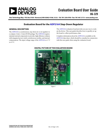
The document provides instructions for setting up the fully assembled and tested ADP2164 evaluation board. It details jumper configurations for enabling output voltage, selecting PWM or external clock synchronization, and adjusting switching frequency via jumpers J7 (RT) and J10 (TRK). The guide also covers proper connections for input power sources, loads, and voltmeters to test points T1 through T5.
Read onlineAnalog Devices ADP2164 specifications
| Continuous Output Current | 4 A |
|---|---|
| Input Voltage Range | 2.7 V to 6.5 V |
| Output Voltage Range | 0.6 V to Vin |
| Switching Frequency (Fixed) | 600 kHz or 1.2 MHz |
| Switching Frequency (Adjustable) | 500 kHz to 1.4 MHz |
| Package Type | 16-lead, 4 mm x 4 mm LFCSP |
| Operating Junction Temperature | -40°C to +125°C |
| Thermal Shutdown Threshold | 140°C |
Source: Analog Devices ADP2164 Datasheet
All Analog Devices ADP2164 documents by type
Day-to-day operation, settings and troubleshooting. Start here if the product is already set up.
Ratings, dimensions and ordering codes, for selection and design work.
Questions answered in these manuals
What is the default output voltage when powered on?
If the input power source is above 2.7 V, the output voltage rises to 1.2 V by default.
How do I set the switching frequency to 600 kHz?
Set jumper J7 (RT) to Low.
What is the output voltage accuracy of the ADP2164?
The output voltage accuracy is specified as +1.5%.
Can the ADP2164 be synchronized to an external clock?
Yes, it is synchronizable from 500 kHz to 1.4 MHz with selectable phase shift of 0° or 180°.