
The ADP2119/ADP2120 Evaluation Board User Guide describes how to quickly set up the board to collect performance data.
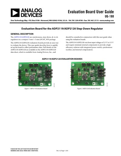
The document provides a user guide (UG-188) for the ADP2119/ADP2120 Evaluation Boards, which are designed to evaluate synchronous step-down dc-to-dc regulators. The boards support input voltages from 2.3 V to 5.5 V and feature integrated power switches and synchronous rectifiers.
| Package Type | 3 mm x 3 mm LFCSP_WD |
|---|---|
| Input Voltage Range | 2.3 V to 5.5 V |
| Default Output Voltage | 1.2 V |
Place the probe tip at Test Point T6 and connect the ground to GND.
The output voltage rises to 1.2 V as the default setting.
The boards run from input voltages of 2.3 V or higher.