
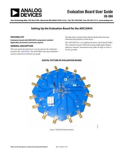
This user guide describes how to set up and use the evaluation board for the ADCLK954.
The document is a user guide for the Analog Devices ADCLK954 evaluation board. It details the package contents, recommended setup procedures involving power supplies and signal sources, and explains how to connect the 12 differential clock outputs to an oscilloscope using matched coaxial cables or probes.
The guide includes diagrams of the board layout, schematic artwork showing trace layers and component placement, and specific instructions for jumper settings. It also provides a list of basic equipment required for evaluation. This manual is written in Chinese.
This user guide describes how to set up and use the evaluation board for the ADCLK954, which is a very high performance clock fanout buffer.
The recommended setup requires V CC to be set to 3.3 V and V EE to be set to GND.
The range of the peak-to-peak input voltage swing at CLK1 is 0.2 V p-p to 1.7 V p-p.