
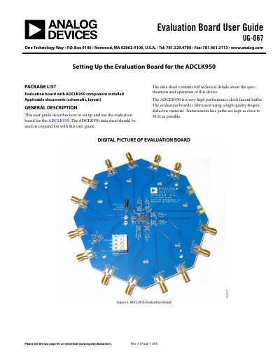
Analog Devices ADCLK950 Evaluation Board User Guide UG-067


Analog Devices ADCLK950 Evaluation Board User Guide UG-067 - cover page
Brand
Analog Devices
Category
Other Electronics
Document type
User Manual
Language
English
Pages
8
File format
PDF
File size
217 KB
Published
02 August, 2012
Updated
29 September, 2023
MD5 checksum
E9E9CC30134FE0732198A0A21A2F2D47

About this manual

This document is a user guide for the Analog Devices ADCLK950 Evaluation Board (UG-067). It provides instructions on setting up the board for device evaluation, detailing the required equipment such as power supplies, signal sources, and oscilloscopes. The guide explains that the ADCLK950 is a very high performance clock fanout buffer fabricated using Rogers dielectric material.

What's inside

  • General Description
  • Evaluation Board Hardware
  • Recommended Board Setup
  • Clock Outputs
  • Evaluation Board Schematic and Artwork
  • ESD Caution

Frequently asked questions

What is the recommended voltage setting for VCC on the evaluation board?

The recommended setup sets VCC to 3.3 V.

What is the acceptable range for the peak-to-peak input voltage swing at CLK1?

The range is 0.2 V p-p to 1.7 V p-p.

How many differential clock outputs does the ADCLK950 have?

The device has 10 differential outputs.

Download PDF (217 KB)

More Analog Devices Manuals


View all Analog Devices manuals →