
Key facts
- Brand
- Texas Instruments
- Model
- CDC5801
- Industry
- Industrial
- Documents
- 3
- Languages
- EN
- Last added
- 2012-08-01
Start here
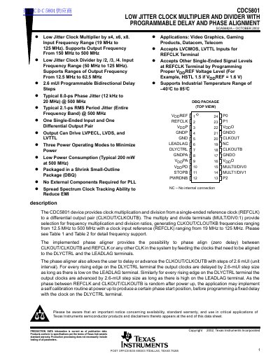
Texas Instruments CDC5801 Low Jitter Clock Multiplier and Divider Datasheet
The CDC5801 is a low jitter clock multiplier and divider device that accepts a single-ended reference clock (REFCLK) and provides a differential output pair (CLKOUT/CLKOUTB). It supports multiplication ratios of x4, x6, and x8, as well as division ratios of /2, /3, and /4, with output frequencies ranging from 12.5 MHz to 500 MHz. The device operates with a reference input frequency between 19 MHz and 125 MHz.
Read onlineTexas Instruments CDC5801 specifications
| Output Frequency Range | 12.5 MHz to 500 MHz |
|---|---|
| Input Frequency Range | 19 MHz to 125 MHz |
| Multiplication Ratios | x4, x6, x8 |
| Division Ratios | /2, /3, /4 |
| Typical Phase Jitter | 8.0-ps |
| Package Type | DBQ |
Source: Texas Instruments CDC5801 Low Jitter Clock Multiplier and Divider Datasheet
All Texas Instruments CDC5801 documents by type
Ratings, dimensions and ordering codes, for selection and design work.
Questions answered in these manuals
What are the multiplication ratios supported by the CDC5801?
The device supports multiplication ratios of x4, x6, and x8.
From: Texas Instruments CDC5801 Low Jitter Clock Multiplier and Divider Datasheet
What are the division ratios available for the CDC5801?
The device supports division ratios of /2, /3, and /4.
From: Texas Instruments CDC5801 Low Jitter Clock Multiplier and Divider Datasheet
How is the programmable delay set on the CDC5801?
Each rising edge on the DLYCTRL terminal advances or delays the output by a 2.6‑mUI step (1/384 of the output period).
From: Texas Instruments CDC5801 Low Jitter Clock Multiplier and Divider Datasheet
What is the typical phase jitter at 500 MHz?
At 500 MHz the accumulated phase jitter is about 8 ps (measured from 50 kHz to 80 MHz).
From: Texas Instruments CDC5801 Low Jitter Clock Multiplier and Divider Datasheet