
Key facts
- Brand
- Texas Instruments
- Model
- SN54HC10
- Category
- Other Electronics
- Documents
- 2
- Languages
- EN
- Last added
- 2012-05-08
Start here
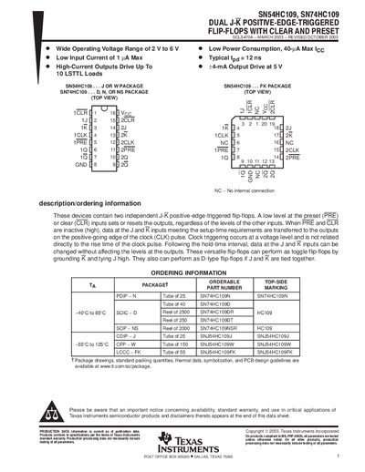
Texas Instruments SN54HC109 / SN74HC109 Dual J‑K Flip‑Flop Datasheet
The SN54HC109 and SN74HC109 are dual J‑K positive‑edge‑triggered flip‑flops with clear and preset inputs. They operate from 2 V to 6 V, consume low power (40 µA max) and feature low input current (1 µA max). The devices can be used as toggle flip‑flops, D‑type flip‑flops, or standard J‑K flip‑flops depending on input configuration.
The datasheet provides absolute maximum ratings, recommended operating conditions, electrical characteristics, switching performance, and detailed packaging information for PDIP, SOIC, SOP, and other package types. Mechanical dimensions and an important notice on product availability and warranty are also included.
Texas Instruments SN54HC10 specifications
| Operating voltage range | 2 V to 6 V |
|---|---|
| Low power consumption | 40 µA max |
| Typical propagation delay | 12 ns |
| High‑current output drive | up to +4 mA at 5 V |
Source: Texas Instruments SN54HC109 / SN74HC109 Dual J‑K Flip‑Flop Datasheet
All Texas Instruments SN54HC10 documents by type
Ratings, dimensions and ordering codes, for selection and design work.
Questions answered in these manuals
What does a low level on the PRE or CLR inputs do?
A low level at the preset (PRE) or clear (CLR) inputs sets or resets the outputs regardless of the other inputs.
From: Texas Instruments SN54HC109 / SN74HC109 Dual J‑K Flip‑Flop Datasheet
What is the operating voltage range of the SN54HC10?
The device operates from 2 V up to 6 V.
From: Texas Instruments SN54HC10 3-Input NAND Gate Datasheet
How many LSTTL loads can the SN54HC10 output drive?
It can drive up to 10 LSTTL loads.
From: Texas Instruments SN54HC10 3-Input NAND Gate Datasheet