
Key facts
- Brand
- Texas Instruments
- Model
- CDCU877
- Industry
- Industrial
- Documents
- 3
- Languages
- EN
- Last added
- 2012-08-01
Start here
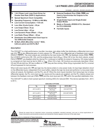
Texas Instruments CDCU877/CDCU877A 1.8-V Phase Lock Loop Clock Driver Datasheet
The CDCU877 is a Zero-delay buffer designed to distribute a differential clock input pair to ten differential pairs of clock outputs and one feedback output. It features low jitter and skew specifications suitable for Double Data Rate (DDR II) applications.
The device operates from an operating frequency range of 10 MHz to 400 MHz and supports spread spectrum clocking (SSC). It is available in a 52-ball BGA package or a 40-pin MLF package.
Texas Instruments CDCU877 specifications
| Low Jitter (Cycle-Cycle) | +30 ps |
|---|---|
| Low Output Skew | 35 ps |
| Operating Temperature Range | -40°C to 85°C |
| Output Distribution | Ten differential outputs |
Source: Texas Instruments CDCU877/CDCU877A 1.8-V Phase Lock Loop Clock Driver Datasheet
All Texas Instruments CDCU877 documents by type
Ratings, dimensions and ordering codes, for selection and design work.
Questions answered in these manuals
Can the CDCU877 handle spread spectrum clocking?
Yes, the device is able to track spread spectrum clocking (SSC) for reduced EMI.
From: Texas Instruments CDCU877/CDCU877A 1.8-V Phase Lock Loop Clock Driver Datasheet
What happens when AVpp is grounded?
When AVpp is grounded, the PLL is turned off and bypassed for test purposes.
From: Texas Instruments CDCU877/CDCU877A 1.8-V Phase Lock Loop Clock Driver Datasheet
What is the operating frequency range of the CDCU877?
The CDCU877 operates from 125 MHz up to 400 MHz.
From: Texas Instruments CDCU877 1.8‑V Phase Clock Loop Clock Driver Datasheet
What supply voltage does the CDCU877 require?
The device requires a supply voltage (Vpp) between 1.7 V and 1.9 V.
From: Texas Instruments CDCU877 1.8‑V Phase Clock Loop Clock Driver Datasheet