
Key facts
- Brand
- Maxim
- Model
- MAX-20
- Category
- Other Electronics
- Documents
- 51
- Languages
- EN · ZH
- Last added
- 2012-05-07
Start here
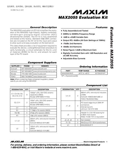
Maxim MAX2055 Evaluation Kit User Manual
The MAX2055 evaluation kit is a fully assembled, factory‑tested board that simplifies evaluation of the MAX2055 high‑linearity, digitally controlled variable‑gain ADC driver. It includes SMA connectors, a 20‑pin TSSOP‑EP package, and a range of components such as inductors, capacitors, and transformers to support operation from 30 MHz to 300 MHz with gain from –3 dB to +20 dB.
The manual offers a quick‑start guide, detailed test procedures, and layout considerations. It explains how to connect power and RF ports, set gain via header pins, measure supply current and power gain, and modify the kit for single‑ended operation. Schematic diagrams and PCB layout figures help users design their own boards based on the evaluation kit.
Maxim MAX-20 specifications
| RF Frequency Range | 850 MHz – 1550 MHz |
|---|---|
| LO Frequency Range | 1200 MHz – 2250 MHz |
| IF Frequency Range | 50 MHz – 1000 MHz |
| Typical Conversion Loss | 7.4 dB |
| Typical Noise Figure | 7.8 dB |
| Typical Input IP3 | +35 dBm |
| Supply Current | 105 mA – 130 mA |
| Package | 5 mm × 5 mm, 20‑pin thin QFN |
Source: Maxim MAX2051 High-Linearity Up/Downconversion Mixer Datasheet
All Maxim MAX-20 documents by type
Ratings, dimensions and ordering codes, for selection and design work.
- Maxim MAX2051 High-Linearity Up/Downconversion Mixer Datasheet 16 p
- Maxim MAX2042 Mixer Handbook 27 p
- Maxim MAX2032 High-Linearity Upconversion/Downconversion Mixer Handbook 19 p
- Maxim MAX2044 High-Linearity Mixer Datasheet 39 p
- Maxim MAX2042A SiGe High-Linearity Mixer Data Sheet 52 p
- Maxim MAX2027 Variable-Gain Amplifier Datasheet 10 p
- Maxim MAX2055 Variable‑Gain Differential ADC Driver Datasheet 13 p
- Maxim MAX2057 Variable-Gain Amplifier Datasheet 13 p
- Maxim Integrated MAX2056 Variable-Gain Amplifier Datasheet 12 p
- Maxim MAX2058 Digital Variable Gain Amplifier Datasheet 15 p
- Maxim MAX2065 High-Linearity Variable Gain Amplifier Datasheet 27 p
- Maxim MAX2066 Digital Variable Gain Amplifier Datasheet 23 p
- Maxim MAX2067 High-Linearity Variable Gain Amplifier Datasheet 23 p
- Maxim MAX2063 Dual Digital Variable-Gain Amplifier Datasheet 22 p
- Maxim MAX2062 Dual Analog/Digital VGA Datasheet 24 p
- Maxim MAX2064 Dual 50MHz‑1000MHz High‑Linearity VGA Datasheet 20 p
- Maxim MAX202E, MAX213E, MAX232E, MAX241E RS-232 Transceiver Datasheet 25 p
- Maxim Integrated MAX2059 High-Linearity DVGA Datasheet 14 p
- Maxim MAX2059 High-Linearity DVGA Datasheet 14 p
- Maxim MAX2058 High-Linearity SPI-Controlled DVGA with Integrated Loopback Mixer Datasheet 15 p
- Maxim MAX2057 Variable‑Gain Amplifier Datasheet 12 p
- Maxim MAX2057 Variable‑Gain Amplifier Data Sheet 12 p
- Maxim MAX2056 Variable‑Gain Amplifier Datasheet 12 p
- Maxim MAX2055 ADC Driver/Amplifier Datasheet 13 p
- Maxim MAX2055 Datasheet 13 p
- Maxim MAX2055 ADC Driver/Amplifier Datasheet 13 p
- Maxim MAX2051 Up/Downconversion Mixer Datasheet 16 p
- MAXIM MAX 20 Series HIGH CURRENT TRANSIENT VOLTAGE SUPPRESSOR (TVS) DIODE VOLTAGE - 5.0 to 150.0 Volts 20000 Watt Peak Pulse Power Manual 4 p
- Maxim MAX200-MAX211/MAX213 Datasheet 20 p
- Maxim MAX2045/MAX2046/MAX2047 High-Gain Vector Multipliers Datasheet 22 p
- Maxim MAX2043 Mixer Datasheet 17 p
- Maxim MAX2041 Datasheet 16 p
- Maxim MAX2039 Mixer Datasheet 16 p
- Maxim MAX2034 Quad-Channel Ultra-Low-Noise Amplifier Datasheet 13 p
- Maxim MAX2031 Mixer Datasheet 16 p
- Maxim MAX202E/MAX213E/MAX232E/MAX241E RS-232 Transceiver Datasheet 25 p
- Maxim MAX202E/MAX213E/MAX232E/MAX241E Datasheet 25 p
- Maxim RS-232 Transceiver Series (MAX202E‑MAX213E, MAX232E/MAX241E) Datasheet 25 p
- Maxim MAX200/MAX209/MAX211/MAX213 Datasheet 23 p
- Maxim MAX202E/MAX213E/MAX232E/MAX241E RS-232 Transceiver Datasheet 25 p
- Maxim MAX2063 Variable Gain Amplifier Datasheet 22 p
Day-to-day operation, settings and troubleshooting. Start here if the product is already set up.
How to use the product for one specific task, with worked examples.
Questions answered in these manuals
What is the typical conversion loss of the MAX2051?
The typical conversion loss is 7.4 dB.
From: Maxim MAX2051 High-Linearity Up/Downconversion Mixer Datasheet
What package is the MAX2051 offered in?
It is offered in a 5 mm × 5 mm, 20‑pin thin QFN package with an exposed pad.
From: Maxim MAX2051 High-Linearity Up/Downconversion Mixer Datasheet
What is the typical supply current at 5 V?
The typical supply current at a 5 V supply is 138 mA.
What package is the MAX2042 offered in?
It is available in a 20‑pin thin QFN‑EP (5 mm × 5 mm) package with an exposed pad.
What is the RF frequency range of the MAX2032?
The MAX2032 supports an RF frequency range from 650 MHz to 1000 MHz.
From: Maxim MAX2032 High-Linearity Upconversion/Downconversion Mixer Handbook
What is the supply current range for the MAX2032?
Supply current is guaranteed to be below 100 mA, typically 85 mA to 100 mA.
From: Maxim MAX2032 High-Linearity Upconversion/Downconversion Mixer Handbook