
The MAX2039 evaluation kit simplifies the evaluation of the MAX2039 UMTS, DCS, and PCS base-station up/downconversion mixer. It is fully assembled and tested at the factory. Standard 50Ω SMA connectors are included on the EV kit’s input and output ports to allow quick and easy evaluation on the test bench.
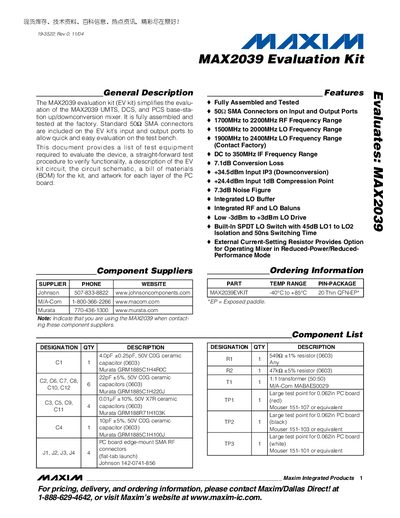
The MAX2039 Evaluation Kit is a fully assembled, factory‑tested board that simplifies evaluation of the MAX2039 UMTS/DCS/PCS base‑station up/downconversion mixer. It includes SMA connectors covering 1700 MHz–2200 MHz RF and 1500 MHz–2000 MHz LO ranges, and provides a convenient platform for functional testing on a bench.
The manual details the required test equipment, step‑by‑step connection and setup procedures, mixer testing methodology, and layout considerations. It also contains the complete schematic, component list, and PCB layout drawings, along with optional modifications to reduce power consumption.
| RF Frequency Range | 1700 MHz to 2200 MHz |
|---|---|
| LO Frequency Range | 1500 MHz to 2000 MHz |
| IF Frequency Range | DC to 350 MHz |
| Conversion Loss | 7.1 dB |
| Input IP3 (Downconversion) | +34.5 dBm |
| 1 dB Compression Point | +24.4 dBm |
| Noise Figure | 7.3 dB |
| LO Drive Range | -3 dBm to +3 dBm |
| LO Switch Isolation | 45 dB |
| LO Switch Switching Time | 50 ns |
You need a DC supply capable of +5.0 V/175 mA, two RF signal generators (10 cBm, 1‑3 GHz), an RF spectrum analyzer (100 kHz‑38 GHz), an RF power meter, and a power sensor.
Connecting the LOSEL pin (TP3) to ground selects LO1; leaving TP3 open selects LO2.
Set the DC supply to +5.0 V and limit the current to about 175 mA.