
The MAX2065 high-linearity, analog/digital variable-gain amplifier (VGA) is designed to operate in the 50MHz to 1000MHz frequency range with two independent attenuators (see the Typical Application Circuit). The digital attenuator is controlled as a slave peripheral using either the SPI-compatible interface or a parallel bus with 31dB total adjustment range in 1dB steps. An added feature allows “rapid-fire” gain selection between each of four steps, preprogrammed by the user through the SPI-compatible interface. The 2-pin control allows the user to quickly access any one of four customized attenuation states without reprogramming the SPI bus. The analog attenuator is controlled using an external voltage or through the SPI-compatible interface using an on-chip 8-bit DAC. Because each of the three stages has its own RF input and RF output, this component can be configured to either optimize NF (amplifier configured first), OIP3 (amplifier last), or a compromise of NF and OIP3. The device’s performance features include 22dB amplifier gain (amplifier only), 6.5dB NF at maximum gain (includes attenuator insertion losses), and a high OIP3 level of +42dBm. Each of these features makes the MAX2065 an ideal VGA for numerous receiver and transmitter applications. In addition, the MAX2065 operates from a single +5V supply with full performance, or a single +3.3V supply with slightly reduced performance, and has an adjustable bias to trade current consumption.
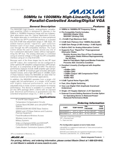
The MAX2065 is a high‑linearity variable‑gain amplifier designed for 50 MHz to 1000 MHz operation. It features two independent attenuators that can be controlled via an SPI‑compatible or parallel interface, providing a total 31 dB digital and 31 dB analog attenuation range.
The device operates from a single +5 V supply (or optional +3.3 V) and is available in a 40‑pin thin QFN package. Electrical performance includes 22 dB amplifier gain, 6.5 dB noise figure at maximum gain, and a high OIP3 of +42 dBm. Temperature range is –40 °C to +85 °C.
| Frequency Range | 50 MHz – 1000 MHz |
|---|---|
| Total Attenuation Range | 61.5 dB (analog + digital) |
| Supply Voltage | 3.0 V – 3.6 V (or 4.75 V – 5.25 V) |
| Supply Current | 60 mA – 80 mA |
| Maximum Gain | 62 dB (31 dB analog + 31 dB digital) |
| Amplifier Gain | 22 dB |
| Noise Figure (max gain) | 6.5 dB |
The combined analog and digital attenuation range is 61.5 dB.