
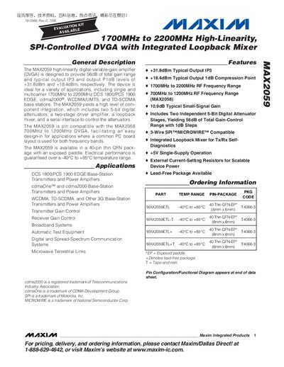
The MAX2059 is a high‑linearity digital‑variable‑gain amplifier (DVGA) covering 1700 MHz to 2200 MHz. It provides up to 56 dB of gain with 1 dB steps, two independent 5‑bit digital attenuators, and a SPI‑compatible control interface. The device is offered in a 40‑pin thin QFN package with an exposed paddle and operates from –40 °C to +85 °C.
Key features include typical output IP3 of +31.8 dBm, typical 1 dB compression point of +18.4 dBm, and a small‑signal gain of 10.9 dB. Electrical specifications cover supply voltage of 4.75 V‑5.25 V, total supply current up to 275 mA, and a maximum clock speed of 38 MHz for the SPI interface. The datasheet also provides absolute‑maximum ratings, DC and AC electrical characteristics, and detailed pin‑configuration diagrams.
| RF Frequency Range | 1700 MHz – 2200 MHz |
|---|---|
| Typical Output IP3 | +31.8 dBm |
| Typical Output 1 dB Compression Point | +18.4 dBm |
| Small‑Signal Gain (typical) | 10.9 dB |
| Supply Voltage | 4.75 V – 5.25 V |
| Digital Attenuator Resolution | 5‑bit |
| Control Interface | 3‑Wire SPI / MICROWIRE compatible |
The MAX2059 operates from 1700 MHz to 2200 MHz.
Typical output third‑order intercept point is +31.8 dBm.
Each digital attenuator is a 5‑bit device.
The attenuators are controlled via a 3‑wire SPI/MICROWIRE compatible interface.