
The document introduces MAX2031 evaluation board, including the features, test methods, circuit diagram, BOM and artwork.
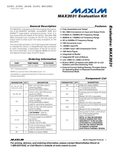
This manual describes the MAX2031 Evaluation Kit, a fully assembled and tested board that implements a high‑linearity up/downconverter with integrated RF and LO baluns, an LO buffer, and a SPDT LO switch. It lists the kit’s features, ordering information, and a complete component bill of materials.
The document includes a quick‑start guide, required test equipment, step‑by‑step connection and setup instructions, mixer testing procedures, detailed descriptions of the internal circuitry, layout considerations, and instructions for modifying the kit for down‑converter operation.
| LO Frequency Range | 960 MHz – 1180 MHz |
|---|---|
| IF Frequency Range | DC – 250 MHz |
| Conversion Loss | 7 dB |
| Input IP3 | +86 dBm |
| 1 dB Compression Point | +27 dBm |
| Noise Figure | 7 dB |
The mixer exhibits a conversion loss of about 7 dB.
Yes, remove the C4/L1 band‑limiting network and install capacitor C5 to improve down‑converter linearity.