
Key facts
- Brand
- STMicroelectronics
- Model
- L9352B
- Industry
- Industrial
- Documents
- 3
- Languages
- EN
- Last added
- 2012-08-08
Start here
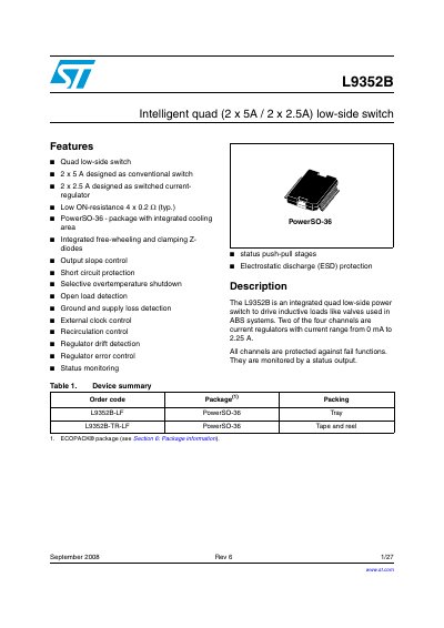
STMicroelectronics L9352B Intelligent Quad Low-Side Switch Datasheet
The L9352B is an integrated quad low-side power switch designed to drive inductive loads such as valves used in ABS systems. It features four channels where two are designed as conventional switches and two as switched current regulators with a range from 0 mA to 2.25 A. The device includes integrated free-wheeling and clamping Z-diodes, status push-pull stages, and output slope control.
Read onlineSTMicroelectronics L9352B specifications
| ON-resistance | 4 x 0.2 Ohm (typ.) |
|---|---|
| Supply voltage | 5 V |
| Package | PowerSO-36 |
Source: STMicroelectronics L9352B Intelligent Quad Low-Side Switch Datasheet
All STMicroelectronics L9352B documents by type
Ratings, dimensions and ordering codes, for selection and design work.
How to use the product for one specific task, with worked examples.
Questions answered in these manuals
What are the two current-regulator channels rated for?
The current-regulator channels (3 and 4) have a current range from 0 mA to 2.25 A.
From: STMicroelectronics L9352B Intelligent Quad Low-Side Switch Datasheet
Does the L9352B include protection for inductive loads?
Yes, it includes integrated free-wheeling and clamping Z-diodes.
From: STMicroelectronics L9352B Intelligent Quad Low-Side Switch Datasheet
What is the current range for the regulator channels?
The two regulated channels have a current range from 0 mA to 2.25 A.
From: STMicroelectronics L9352B Intelligent Quad Low-Side Switch Datasheet
Does the device include short circuit protection?
Yes, all channels are protected against fail functions including short circuit protection.
From: STMicroelectronics L9352B Intelligent Quad Low-Side Switch Datasheet
What is the L9352B designed to drive?
The L9352B is designed to drive inductive loads such as relays and electromagnetic valves in a low side configuration.
From: STMicroelectronics AN2791 L9352B Coil Driver Application Note
What is the frequency of the PWM signal used to define the target output current?
A PWM signal with a 2 kHz frequency on the input defines the target for the output current.
From: STMicroelectronics AN2791 L9352B Coil Driver Application Note