
Key facts
- Brand
- Texas Instruments
- Model
- UC2525A
- Industry
- Industrial
- Documents
- 2
- Languages
- EN
- Last added
- 2012-08-03
Start here
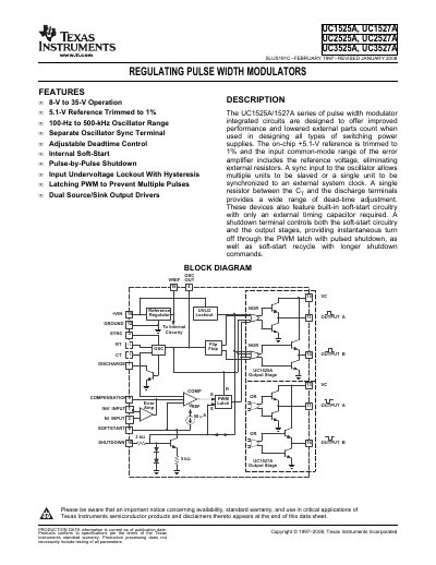
Texas Instruments UC1525A/UC1527A/UC2525A/UC2527A/UC3525A/UC3527A Regulating Pulse Width Modulators Datasheet
Datasheet 13 pages · 350 KB · EN
This document is a datasheet for the UC1525A, UC1527A, UC2525A, UC2527A, UC3525A, and UC3527A series of regulating pulse width modulator integrated circuits. These devices are designed to offer improved performance and a lowered external parts count for switching power supplies. Key features include an 8-V to 35-V operation range, a 5.1-V reference trimmed to 1%, a 100-Hz to 500-kHz oscillator range, adjustable deadtime control, and internal soft-start circuitry.
Read onlineTexas Instruments UC2525A specifications
| Operating Voltage Range | 8 V to 35 V |
|---|---|
| Reference Voltage | 5.1 V |
| Oscillator Frequency Range | 100 Hz to 500 kHz |
| Output Current (Source or Sink) | 200 mA |
| Operating Junction Temperature | -55 to 150 C |
| Power Dissipation (Ta = +25C) | 1000 mW |
All Texas Instruments UC2525A documents by type
Datasheet 2
Ratings, dimensions and ordering codes, for selection and design work.
Questions answered in these manuals
What is the typical output voltage of the reference?
The reference output voltage is typically 5.1 V.
What is the maximum duty cycle supported?
The maximum duty cycle is 49%.