
Key facts
- Brand
- Texas Instruments
- Model
- TL1591
- Category
- Other Electronics
- Documents
- 2
- Languages
- EN
- Last added
- 2012-08-09
Start here
Texas Instruments TL1591 Sample-and-Hold Circuit Datasheet
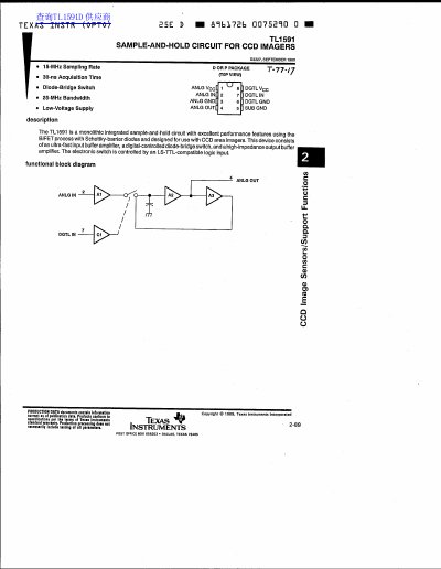
The TL1591 is a monolithic integrated sample-and-hold circuit designed for use with CCD area imagers. It utilizes a BIFET process with Schottky-barrier diodes and consists of an ultra-fast input buffer amplifier, a digitally controlled diode-bridge switch, and a high-impedance output buffer amplifier. The electronic switch is controlled by an LS-TTL-compatible logic input.
Read onlineTexas Instruments TL1591 specifications
| Acquisition Time | 30 ns |
|---|---|
| Bandwidth | 25 MHz |
| Operating Temperature Range | -25°C to 80°C |
| Storage Temperature Range | -55°C to 160°C |
| Linearity | 0.7% |
Source: Texas Instruments TL1591 Sample-and-Hold Circuit Datasheet
All Texas Instruments TL1591 documents by type
Ratings, dimensions and ordering codes, for selection and design work.
Questions answered in these manuals
What is the TL1591 designed for?
It is designed for use with CCD area imagers.
From: Texas Instruments TL1591 Sample-and-Hold Circuit Datasheet
What is the typical linearity?
The typical linearity is 0.7%.
From: Texas Instruments TL1591 Sample-and-Hold Circuit Datasheet
What is the TL1591 designed for?
The TL1591 is designed for use with CCD area imagers.
What is the typical acquisition time?
The typical acquisition time is 31 ns for a 0.6 V to 1% error band.