
Key facts
- Brand
- STMicroelectronics
- Model
- ST10F280
- Category
- microcontrollers
- Documents
- 4
- Languages
- EN
- Last added
- 2012-08-08
Start here
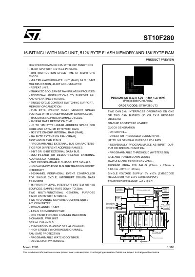
STMicroelectronics ST10F280 16-Bit MCU Datasheet
The ST10F280 is a derivative of the STMicroelectronics ST10 family of 16-bit single-chip CMOS microcontrollers. It combines high CPU performance with high peripheral functionality, including an on-chip Multiply-Accumulate (MAC) unit for DSP functions and enhanced I/O capabilities.
The device features up to 512K bytes of on-chip Flash memory with a single voltage erase/program controller and 18K bytes of RAM. It operates at a maximum CPU frequency of 40MHz and includes two CAN 2.0b interfaces, an A/D converter, PWM modules, and various serial communication channels.
STMicroelectronics ST10F280 specifications
| CPU Architecture | 16-BIT CPU WITH 4-STAGE PIPELINE |
|---|---|
| Instruction Cycle Time | 50ns at 40MHz CPU CLOCK |
| RAM Size (Internal) | 2K BYTE |
| RAM Size (Extension) | 16K BYTE |
| Maximum CPU Frequency | 40MHz |
| Supply Voltage | 5V +10% |
| Operating Temperature Range | -40 to +125C |
| Flash Endurance | 100K ERASING/PROGRAMMING CYCLES |
All STMicroelectronics ST10F280 documents by type
Ratings, dimensions and ordering codes, for selection and design work.
How to use the product for one specific task, with worked examples.
Questions answered in these manuals
What is the maximum CPU frequency of the ST10F280?
The maximum CPU frequency is 40MHz.
How much Flash memory does the device contain?
It contains 512K bytes of on-chip Flash memory.
What is the primary design purpose of the ST10F280 device?
The device is specifically designed for applications based on the C167 that require signal processing.
What new feature was added to the ST10F280 for signal sampling?
A timer was added to allow automatic triggering of ADC requests on a pre-defined time period.
What causes analog input signal error?
Analog input signal error can be caused by poor matching of source internal resistance with ADC input parameters, voltage drops due to leakage current, or noise from the analog input signal.
How can high frequency errors be avoided?
The input analog signal should always be low pass filtered to ensure that high frequencies are rejected during the sampling time.