
Key facts
- Brand
- Maxim
- Model
- MAX8725
- Industry
- Industrial
- Documents
- 2
- Languages
- EN · ZH
- Last added
- 2012-05-08
Start here
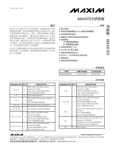
Maxim MAX8725 Evaluation Board User Manual
The MAX8725 evaluation board is a high‑precision, high‑efficiency charger that supports three to four series‑connected Li‑ion cells with up to 3 A charging current. Input voltage ranges from +8 V to +25 V, and the board provides adjustable charging voltage and current via on‑board potentiometers and jumpers.
The manual includes an overview, component list, quick‑start steps, jumper settings, voltage and current limit adjustments, and detailed PCB layout diagrams to help users set up and verify the board’s operation. This manual is written in Chinese.
Maxim MAX8725 specifications
| Input Voltage Range | 8.0 V – 28 V |
|---|---|
| Output Voltage (LDO) | 5.25 V – 5.55 V (no load) |
| Maximum Input Voltage | 28 V |
| Programmable Charge Current | up to >4 A |
| Operating Temperature Range | -40 °C to +85 °C |
| Efficiency | >95 % |
| Package | 28‑pin Thin QFN |
| Charge Voltage Accuracy | ±0.5 % (0 °C to +85 °C) |
Source: Maxim MAX1909/MAX8725 Multichemistry Battery Charger Datasheet
All Maxim MAX8725 documents by type
Day-to-day operation, settings and troubleshooting. Start here if the product is already set up.
Ratings, dimensions and ordering codes, for selection and design work.
Questions answered in these manuals
What is the maximum input voltage the MAX1909/MAX8725 can handle?
The devices are rated for a maximum input voltage of 28 V.
From: Maxim MAX1909/MAX8725 Multichemistry Battery Charger Datasheet
How much charge current can be programmed on the MAX1909/MAX8725?
The charge current is programmable up to more than 4 A.
From: Maxim MAX1909/MAX8725 Multichemistry Battery Charger Datasheet
How do I set the number of battery cells for charging?
Set jumper JU1 to the position that matches the number of series cells; the default position is for 4 cells.
How is the MAX8725 enabled after wiring the board?
Install the shorting jumper on JU2; this connects the PKPRES pin and enables the MAX8725.