
The MAX1909/MAX8725 are highly integrated control ICs that simplify the construction of accurate and efficient multi-chemistry battery chargers. The MAX1909/MAX8725 use analog inputs to control charge current and voltage, and can be programmed by a host microcontroller (µC) or hardwired. High efficiency is achieved through use of buck topology with synchronous rectification. The maximum current drawn from the AC adapter is programmable to avoid overloading the AC adapter when supplying the load and the battery charger simultaneously. The MAX1909/MAX8725 provide a digital output that indicates the presence of an AC adapter, and an analog output that monitors the current drawn from the AC adapter. Based on the presence or absence of the AC adapter, the MAX1909/MAX8725 automatically select the appropriate source for supplying power to the system by controlling two external p-channel MOSFETs. Under system control, the MAX1909/MAX8725 allow the battery to undergo a relearning or conditioning cycle in which the battery is completely discharged through the system load and then recharged. The MAX1909 includes a conditioning charge feature while the MAX8725 does not. The MAX1909/MAX8725 are available in space-saving 28-pin, 5mm × 5mm thin QFN packages and operate over the extended -40°C to +85°C temperature range. The MAX1909/MAX8725 are now available in lead-free packages.
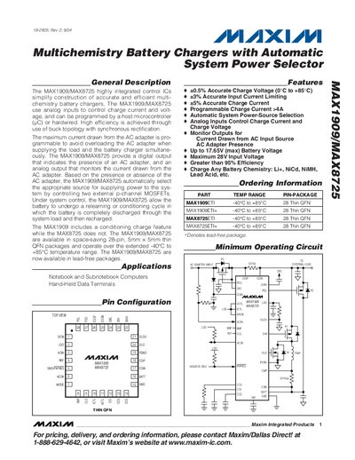
The MAX1909 and MAX8725 are highly integrated control ICs that simplify the design of accurate, efficient multichemistry battery chargers. They use analog inputs to control charge current and voltage and can be programmed by a host microcontroller or hard‑wired. The devices include a digital AC‑adapter‑presence output and an analog current‑monitor output, and they automatically select the appropriate power source by controlling external p‑channel MOSFETs.
The ICs support charge currents up to more than 4 A, operate over a temperature range of –40 °C to +85 °C, and achieve greater than 95 % efficiency. They are offered in a space‑saving 28‑pin thin QFN package and are available in lead‑free versions. Applications include notebook and sub‑notebook computers, hand‑held data terminals, and system power selectors.
| Input Voltage Range | 8.0 V – 28 V |
|---|---|
| Output Voltage (LDO) | 5.25 V – 5.55 V (no load) |
| Maximum Input Voltage | 28 V |
| Programmable Charge Current | up to >4 A |
| Operating Temperature Range | -40 °C to +85 °C |
| Efficiency | >95 % |
| Package | 28‑pin Thin QFN |
| Charge Voltage Accuracy | ±0.5 % (0 °C to +85 °C) |
The devices are rated for a maximum input voltage of 28 V.
The charge current is programmable up to more than 4 A.
They operate from –40 °C to +85 °C.
Both ICs are available in a 28‑pin thin QFN package.