
Key facts
- Brand
- Maxim
- Model
- MAX2039
- Industry
- Industrial
- Documents
- 3
- Languages
- EN
- Last added
- 2012-05-07
Start here
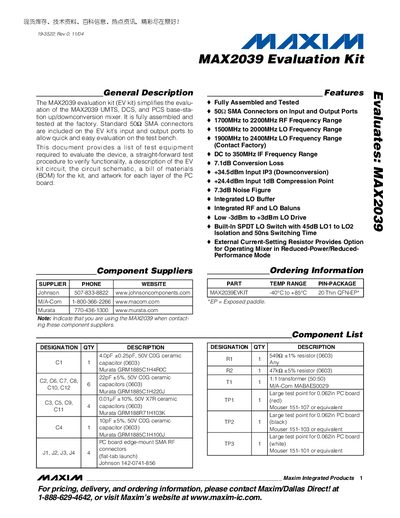
Maxim MAX2039 Evaluation Kit User Manual
The MAX2039 Evaluation Kit is a fully assembled, factory‑tested board that simplifies evaluation of the MAX2039 UMTS/DCS/PCS base‑station up/downconversion mixer. It includes SMA connectors covering 1700 MHz–2200 MHz RF and 1500 MHz–2000 MHz LO ranges, and provides a convenient platform for functional testing on a bench.
The manual details the required test equipment, step‑by‑step connection and setup procedures, mixer testing methodology, and layout considerations. It also contains the complete schematic, component list, and PCB layout drawings, along with optional modifications to reduce power consumption.
Maxim MAX2039 specifications
| RF Frequency Range | 1700 MHz – 2200 MHz |
|---|---|
| Conversion Loss | 7.1 dB |
| Noise Figure | 7.3 dB |
| Input IP3 (Downconversion) | +34.5 dBm |
| Supply Current (max) | 135 mA |
Source: Maxim Integrated MAX2039 High-Linearity Up/Downconverter Mixer Datasheet
All Maxim MAX2039 documents by type
Day-to-day operation, settings and troubleshooting. Start here if the product is already set up.
Ratings, dimensions and ordering codes, for selection and design work.
Questions answered in these manuals
What is the maximum supply current of the MAX2039?
The device draws up to 135 mA of supply current.
From: Maxim Integrated MAX2039 High-Linearity Up/Downconverter Mixer Datasheet
What is the conversion loss of the MAX2039 mixer?
The conversion loss is specified as 7.1 dB.
From: Maxim Integrated MAX2039 High-Linearity Up/Downconverter Mixer Datasheet
What is the RF frequency range of the MAX2039?
The MAX2039 operates from 1700 MHz to 2200 MHz.
What is the conversion loss of the MAX2039?
The typical conversion loss is about 7.1 dB.
What test equipment is required to evaluate the MAX2039?
You need a DC supply capable of +5.0 V/175 mA, two RF signal generators (10 cBm, 1‑3 GHz), an RF spectrum analyzer (100 kHz‑38 GHz), an RF power meter, and a power sensor.
How do you select LO1 or LO2 on the evaluation kit?
Connecting the LOSEL pin (TP3) to ground selects LO1; leaving TP3 open selects LO2.