
Key facts
- Brand
- Maxim
- Model
- MAX2051
- Industry
- Industrial
- Documents
- 2
- Languages
- EN
- Last added
- 2012-05-07
Start here
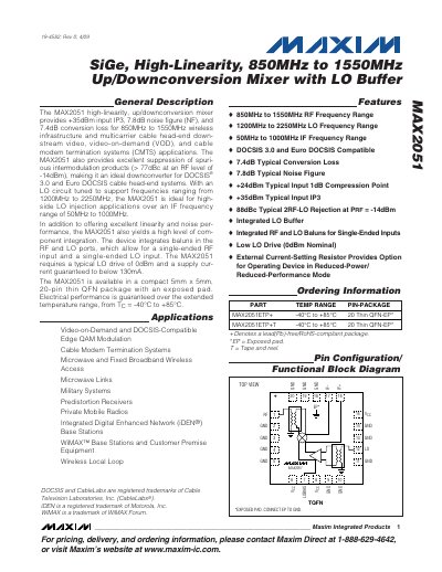
Maxim MAX2051 High-Linearity Up/Downconversion Mixer Datasheet
The MAX2051 provides high linearity and low noise performance for broadband wireless and cable‑head‑end applications. It integrates RF and LO baluns, a low‑drive LO buffer, and supports single‑ended RF and LO inputs. Typical specifications include +35 dBm input IP3, 7.8 dB noise figure, and 7.4 dB conversion loss.
The device operates from –40 °C to +85 °C, is supplied at 4.75‑5.5 V, and draws up to 130 mA. It is offered in a 5 mm × 5 mm, 20‑pin thin QFN package with an exposed pad for thermal management. The mixer supports RF frequencies from 850 MHz to 1550 MHz, LO frequencies from 1200 MHz to 2250 MHz, and IF frequencies from 50 MHz to 1000 MHz.
Maxim MAX2051 specifications
| RF Frequency Range | 850 MHz – 1550 MHz |
|---|---|
| LO Frequency Range | 1200 MHz – 2250 MHz |
| IF Frequency Range | 50 MHz – 1000 MHz |
| Typical Conversion Loss | 7.4 dB |
| Typical Noise Figure | 7.8 dB |
| Typical Input IP3 | +35 dBm |
| Supply Current | 105 mA – 130 mA |
| Package | 5 mm × 5 mm, 20‑pin thin QFN |
Source: Maxim MAX2051 High-Linearity Up/Downconversion Mixer Datasheet
All Maxim MAX2051 documents by type
Ratings, dimensions and ordering codes, for selection and design work.
Questions answered in these manuals
What is the typical conversion loss of the MAX2051?
The typical conversion loss is 7.4 dB.
From: Maxim MAX2051 High-Linearity Up/Downconversion Mixer Datasheet
What package is the MAX2051 offered in?
It is offered in a 5 mm × 5 mm, 20‑pin thin QFN package with an exposed pad.
From: Maxim MAX2051 High-Linearity Up/Downconversion Mixer Datasheet
What LO drive level does the MAX2051 require?
The device requires a typical LO drive of 0 dBm.
How should the exposed pad be connected on the PCB?
The exposed pad must be connected to the ground plane of the PCB, preferably with multiple vias.