Maxim 60MSPS Manuals

We have 4 manuals for the Maxim 60MSPS: 4 Datasheets. Free to view online or download as PDF.

Maxim 60MSPS manuals

MAXIM MAX1002 Low-Power 60Msps Dual 6-Bit ADC handbook

Datasheet

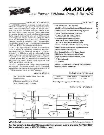
The MAX1002 is a dual, 6-bit analog-to-digital converter (ADC) that combines high-speed, low-power operation with a user-selectable input range, an internal reference, and a clock oscillator. The dual, parallel ADCs are designed to convert in-phase (I) and quadrature (Q) analog signals into two 6-bit offset-binary-coded digital outputs at sampling rates up to 60Msps while achieving typical integral nonlinearity (INL) and differential nonlinearity (DNL) of ±1/4LSB. The ability to interface directly with baseband I and Q signals makes the MAX1002 ideal for use in direct-broadcast satellite, VSAT, and QAM16 demodulation applications. The MAX1002 input amplifiers feature true differential inputs, a 55MHz -0.5dB analog bandwidth, and user-programmable input full-scale ranges of 125mVp-p, 250mVp-p, or 500mVp-p. With an AC-coupled input signal, matching performance between input channels is typically 0.1dB gain, 1/4LSB offset, and 0.5° phase. Dynamic performance is 5.85 effective number of bits (ENOB) with a 20MHz analog input signal, or 5.78 ENOB with a 50MHz input signal. The MAX1002 operates with a single +5V power supply and provides TTL-compatible digital outputs. The device is available in the commercial temperature range (0°C to +70°C) and comes in a 36-pin SSOP package.

MAXIM MAX1446 10-Bit 60Msps 3.0V Low-Power ADC with Internal Reference handbook

Datasheet

The MAX1446 is a 10-bit, 3V analog-to-digital converter (ADC) with a fully differential input, a pipelined 10-stage ADC architecture with digital error correction, and wideband track and hold (T/H) incorporating a fully differential signal path. This ADC is optimized for low-power, high dynamic performance applications in imaging and digital communications. The MAX1446 operates from a single 2.7V to 3.6V supply, consuming only 90mW while delivering a 59.5dB signal-to-noise ratio (SNR) at a 20MHz input frequency. The fully differential input stage has a 400MHz, -3dB bandwidth and may be operated with single-ended inputs. In addition to low operating power, the MAX1446 features a 5µA power-down mode for idle periods. An internal 2.048V precision bandgap reference is used to set the ADC full-scale range. A flexible reference structure allows the user to supply a buffered, direct or externally derived reference for applications requiring increased accuracy or a different input voltage range. Lower and higher speed, pin-compatible versions of the MAX1446 are also available. Refer to the MAX1444 data sheet for a 40Msps version, the MAX1448 data sheet for an 80Msps version, and the MAX1449 data sheet for a 105Msps version. The MAX1446 has parallel, offset binary, three-state outputs that can be operated from 1.7V to 3.3V to allow flexible interfacing. The device is available in a 5mm x 5mm, 32-pin TQFP package and is specified over the extended industrial (-4) temperature range.

MAXIM MAX1420 12-Bit 60Msps 3.3V Low-Power ADC with Internal Reference handbook

Datasheet

The MAX1420 is a 3.3V, 12-bit analog-to-digital converter (ADC) with a fully-differential input, pipelined, 12-stage ADC architecture featuring wideband track-and-hold (T/H) and digital error correction. It is designed for low-power, high dynamic performance applications in imaging and digital communications. The ADC operates from a single 3.3V supply and consumes only 221mW. The fully-differential input stage has a small signal -3dB bandwidth of 400MHz and can be operated with single-ended inputs. The full-scale range of the ADC is set by an internal 2.048V precision bandgap reference. The ADC also features a flexible reference structure that allows for an internal reference or externally applied buffered or unbuffered reference for applications requiring increased accuracy and a different input voltage range. In addition to low operating power, the MAX1420 offers two power-down modes: reference power-down and shutdown mode. In reference power-down mode, the internal bandgap reference is deactivated, resulting in a typical 2mA reduction in supply current. The full shutdown mode is available to maximize power savings during idle periods. The MAX1420 provides parallel, offset binary, CMOS-compatible three-state outputs. It is available in a 7mm x 7mm x 1.4mm, 48-

MAXIM MAX1197 Dual 8-Bit 60Msps 3V Low-Power ADC with Internal Reference Parallel Outputs handbook

Datasheet

The MAX1197 is a 3V, dual, 8-bit analog-to-digital converter (ADC) featuring fully differential wideband track-and-hold (T/H) inputs, driving two ADCs. The MAX1197 is optimized for low-power, small size, and high-dynamic performance for applications in imaging, instrumentation, and digital communications. This ADC operates from a single 2.7V to 3.6V supply, consuming only 120mW while delivering a typical signal-to-noise and distortion (SINAD) of 48.5dB at an input frequency of 30MHz and a sampling rate of 60Msps. The T/H-driven input stages incorporate 400MHz (-3dB) input amplifiers. The converters may also be operated with single-ended inputs. In addition to low operating power, the MAX1197 features a 3mA sleep mode as well as a 0.1µA power-down mode to conserve power during idle periods. An internal 2.048V precision bandgap reference sets the full-scale range of the ADC. A flexible reference structure allows the use of this internal or an externally applied reference, if desired, for applications requiring increased accuracy or a different input voltage range. The MAX1197 features parallel, CMOS-compatible three-state outputs. The digital output format can be set to two’s complement or straight offset binary through a single control pin. The device provides for a separate output power supply of 1.7V to 3.6V for flexible interfacing with various logic families. The MAX1197 is available in a 7mm x 7mm, 48-pin TQFP package, and is specified for