
Key facts
- Brand
- Analog Devices
- Model
- ADP1621
- Industry
- Industrial
- Documents
- 2
- Languages
- EN
- Last added
- 2012-05-05
Start here
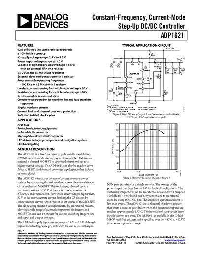
Analog Devices ADP1621 Datasheet Handbook
The ADP1621 is a fixed‑frequency, pulse‑width‑modulation (PWM) current‑mode step‑up converter controller that drives an external n‑channel MOSFET to raise the input voltage. It can also be used in flyback, SEPIC, and forward topologies, both isolated and non‑isolated.
The handbook provides detailed specifications, pin descriptions, typical application circuits, performance graphs, thermal data, and design guidelines such as component selection, slope‑compensation, and synchronization methods.
Analog Devices ADP1621 specifications
| Input voltage range | 2.9 V to 5.5 V |
|---|---|
| Operating frequency range | 100 kHz to 1.5 MHz |
| Internal soft‑start time | 2048 cycles |
| Thermal shutdown temperature | 150 °C |
| Efficiency | up to 92 % |
All Analog Devices ADP1621 documents by type
Ratings, dimensions and ordering codes, for selection and design work.
Questions answered in these manuals
What is the input voltage range of the ADP1621?
The device operates from 2.9 V up to 5.5 V, and can accept as low as 1 V for special low‑power applications.
How is the switching frequency set?
A resistor connected to the FREQ pin sets the free‑running frequency between 100 kHz and 1.5 MHz, and the frequency can be synchronized to an external clock via the SDSN pin.
What is the input voltage range for the ADP1621?
The device operates with an input supply voltage from 2.9 V up to 5.5 V.
From: Analog Devices ADP1621 Step‑Up DC/DC Controller Datasheet
How is the switching frequency set?
The switching frequency is programmed by connecting an external resistor to the FREQ pin, allowing a range of 100 kHz to 1.5 MHz.
From: Analog Devices ADP1621 Step‑Up DC/DC Controller Datasheet