
Key facts
- Brand
- Analog Devices
- Model
- ADP1655
- Industry
- Industrial
- Documents
- 2
- Languages
- EN
- Last added
- 2012-05-03
Start here
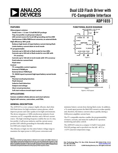
Analog Devices ADP1655 Dual LED Flash Driver Datasheet
The ADP1655 dual LED flash driver is designed for camera‑enabled mobile phones, digital cameras and camcorders. It integrates a 2 MHz synchronous boost converter, an I2C‑compatible control interface and a high‑efficiency LED current source, allowing up to 500 mA flash current for a single LED or 400 mA for two LEDs. The device is packaged in a 12‑ball 0.5 mm pitch WLCSP and operates from 2.7 V to 5.5 V input voltage.
The datasheet provides detailed specifications, pin descriptions, timing diagrams, safety features such as thermal shutdown at 150 °C and over‑voltage protection, as well as recommended external component values and PCB layout guidelines to ensure low EMI and reliable operation.
Analog Devices ADP1655 specifications
| Input Voltage Range | 2.7 V – 5.5 V |
|---|---|
| Input Logic Low Voltage | 0.54 V |
| Input Logic High Voltage | 1.26 V |
| Switching Frequency | 1.85 MHz – 2.15 MHz |
| Overvoltage Threshold | 9.0 V – 10.1 V |
Source: Analog Devices ADP1655 Dual LED Flash Driver Datasheet
All Analog Devices ADP1655 documents by type
Ratings, dimensions and ordering codes, for selection and design work.
Questions answered in these manuals
What is the input voltage range of the ADP1655?
The device operates from 2.7 V to 5.5 V input voltage.
From: Analog Devices ADP1655 Dual LED Flash Driver Datasheet
How is the ADP1655 programmed?
It uses an I2C‑compatible interface that allows programming of timers, LED currents and reading status bits.
From: Analog Devices ADP1655 Dual LED Flash Driver Datasheet
What is the maximum flash current for a single LED?
In flash mode with one LED, the driver can source up to 500 mA.
How can the ADP1655 be programmed?
The driver uses an I²C‑compatible interface that allows programming of timers, currents and status‑bit readback.