
Key facts
- Brand
- Maxim
- Model
- MAX510
- Industry
- Industrial
- Documents
- 2
- Languages
- EN
- Last added
- 2012-06-07
Start here
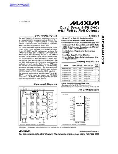
Maxim MAX509/MAX510 Quad Serial-Input 8-Bit DAC Datasheet
The document describes the MAX509 and MAX510 devices as quad, serial-input, 8-bit voltage-output digital-to-analog converters (DACs) that operate with a single +5V supply or dual supplies. These devices feature internal precision buffers that swing rail-to-rail, allowing for full-scale output ranges independent of the reference input.
Read onlineMaxim MAX510 specifications
| Resolution | 8-bit |
|---|---|
| Supply Voltage | +5V or Dual +5V |
| Interface Compatibility | Microwire, SPI/QSPI |
| Clock Frequency | 10 MHz |
| Operating Temperature (Industrial) | -40°C to +85°C |
Source: Maxim MAX509/MAX510 Quad Serial-Input 8-Bit DAC Datasheet
All Maxim MAX510 documents by type
Ratings, dimensions and ordering codes, for selection and design work.
Questions answered in these manuals
Do the output buffers swing rail-to-rail?
Yes, internal precision buffers swing rail-to-rail.
From: Maxim MAX509/MAX510 Quad Serial-Input 8-Bit DAC Datasheet
What is the maximum continuous power dissipation for a 16-pin Plastic DIP package?
The device dissipates up to 842mW in this package.
From: Maxim MAX509/MAX510 Quad Serial-Input 8-Bit DAC Datasheet
What supply voltage does the MAX509 operate from?
It can operate from a single +5 V supply or from dual +5 V supplies.
Which serial interfaces are supported by the MAX509/MAX510?
Both devices support Microwire™, SPI, and QSPI™ serial interfaces.