
Key facts
- Brand
- Analog Devices
- Model
- AD558
- Industry
- Industrial
- Documents
- 2
- Languages
- EN
- Last added
- 2012-05-09
Start here
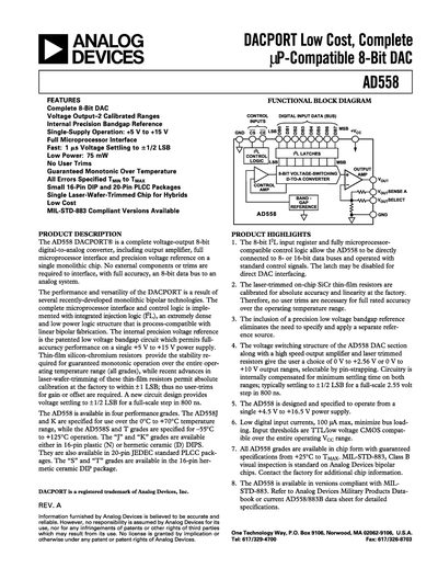
Analog Devices AD558 DACPORT Datasheet
The AD558 DACPORT® is a complete 8‑bit digital‑to‑analog converter that integrates the output amplifier, precision bandgap reference and full microprocessor interface on a single monolithic chip. No external components or user trims are required, and the device operates from a single +4.5 V to +16.5 V supply.
The datasheet provides detailed specifications, pin configurations for DIP and PLCC packages, recommended grounding and bypassing practices, and example interfacing circuits for common microprocessor buses. It also lists the available performance grades, temperature ranges, and MIL‑STD‑883 qualified versions.
Analog Devices AD558 specifications
| Resolution | 8 bits |
|---|---|
| Digital input current | ≤ 100 pA |
| Minimum supply for 10 V range | +11.4 V |
All Analog Devices AD558 documents by type
Ratings, dimensions and ordering codes, for selection and design work.
Questions answered in these manuals
What supply voltage is required for the 0 V to 10 V output range?
A minimum supply voltage of +11.4 V is required for the 0 V to 10 V range.
What is the resolution of the AD558?
The AD558 provides an 8‑bit resolution.
What minimum supply voltage is required for the 0‑10 V output range?
A supply voltage of at least +11.4 V is required for the 0‑10 V output range.
What is the settling time for a full‑scale step?
The device settles to +1/2 LSB for a full‑scale step in about 800 ns.