
Key facts
- Brand
- Motorola
- Model
- TIP120
- Industry
- Industrial
- Documents
- 2
- Languages
- EN
- Last added
- 2012-08-08
Start here
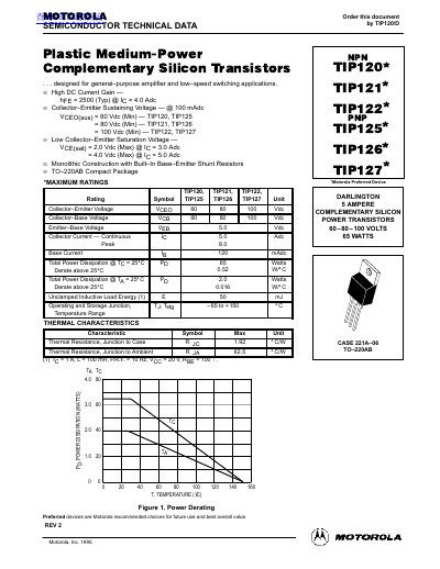
MOTOROLA TIP120 TIP121 TIP122 TIP122 TIP125 TIP126 TIP127 handbook
This document provides technical data for the Motorola TIP120, TIP121, TIP122, TIP125, TIP126, and TIP127 series of plastic medium-power complementary silicon transistors. These devices are designed for general-purpose amplifier and low-speed switching applications.
Read onlineMotorola TIP120 specifications
| Collector-Emitter Sustaining Voltage (TIP121, TIP126) | 80 Vdc |
|---|---|
| Collector-Emitter Sustaining Voltage (TIP122, TIP127) | 100 Vdc |
| Collector Current Continuous | 5.0 Adc |
| Total Power Dissipation (Tg = 25°C) | 65 Watts |
| Operating and Storage Junction Temperature Range | -65 to +150 °C |
Source: MOTOROLA TIP120 TIP121 TIP122 TIP122 TIP125 TIP126 TIP127 handbook
All Motorola TIP120 documents by type
Ratings, dimensions and ordering codes, for selection and design work.
Questions answered in these manuals
What are the applications for these transistors?
They are designed for general-purpose amplifier and low-speed switching applications.
From: MOTOROLA TIP120 TIP121 TIP122 TIP122 TIP125 TIP126 TIP127 handbook
What is the package type?
The devices use a TO-220AB compact package with monolithic construction.
From: MOTOROLA TIP120 TIP121 TIP122 TIP122 TIP125 TIP126 TIP127 handbook
What is the maximum collector‑emitter voltage for TIP120?
The TIP120 is rated for a maximum collector‑emitter voltage of 60 V.
From: Motorola TIP120 TIP121 TIP122 TIP125 TIP126 TIP127 Datasheet
What is the typical DC current gain of these transistors?
The typical DC current gain (hFE) is about 2500 at a collector current of 4 A.
From: Motorola TIP120 TIP121 TIP122 TIP125 TIP126 TIP127 Datasheet