
Key facts
- Brand
- Toshiba
- Model
- TLP250
- Industry
- Industrial
- Documents
- 5
- Languages
- EN
- Last added
- 2012-06-01
Start here
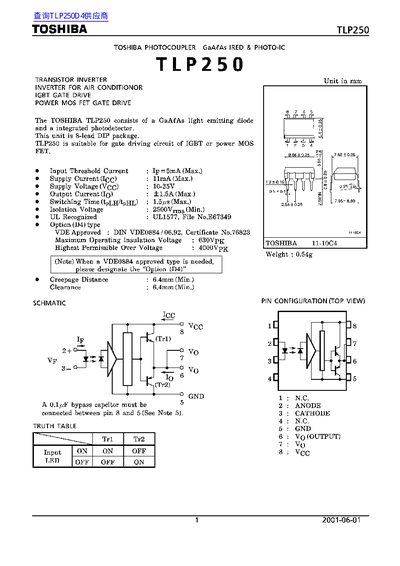
Toshiba TLP250 Optocoupler Datasheet
The TLP250 is a GaAs light‑emitting diode and integrated photodetector optocoupler in an 8‑lead DIP package, intended for gate‑driving circuits of IGBT or power MOSFET devices. The document describes its construction, pin configuration, and recommended application notes such as a 0.1 µF bypass capacitor between pins 8 and 5.
Key electrical ratings are listed, including absolute maximum ratings, recommended operating conditions, and switching characteristics. The datasheet also contains test circuit examples, performance graphs, and a section on restrictions for product use and safety considerations.
Toshiba TLP250 specifications
| Input current (Ip) | 100 mA |
|---|---|
| Output / Total Power Dissipation | 800 mW |
| Maximum operating temperature | 150 °C |
| Insulation resistance (500 V, 25 °C) | 102 Ω |
| Minimum creepage distance | 6.4 mm (TLP250) / 8.0 mm (TLP250F) |
| Minimum clearance distance | 6.4 mm (TLP250) / 8.0 mm (TLP250F) |
| Input‑to‑output test voltage, Method A | 945 V (TLPxxx) / 1710 V (TLPxxxF) |
| Input‑to‑output test voltage, Method B | 1180 V (TLPxxx) / 2140 V (TLPxxxF) |
| Highest permissible overvoltage | 4000 V (TLPxxx) / 6000 V (TLPxxxF) |
Source: TOSHIBA TLP250(D4)/TLP250F(D4)/TLP251(D4)/TLP251F(D4) Manual
All Toshiba TLP250 documents by type
Ratings, dimensions and ordering codes, for selection and design work.
Questions answered in these manuals
What package type does the TLP250 use?
The TLP250 is supplied in an 8‑lead DIP package.
What bypass capacitor is recommended for stable operation?
A 0.1 µF ceramic capacitor should be connected between pin 8 and pin 5.
What is the maximum input current for the TLP250 series?
The maximum input current is 100 mA.
From: TOSHIBA TLP250(D4)/TLP250F(D4)/TLP251(D4)/TLP251F(D4) Manual
What are the minimum creepage and clearance distances?
The minimum creepage distance is 6.4 mm for TLP250 and 8.0 mm for TLP250F; the minimum clearance distance is the same values.
From: TOSHIBA TLP250(D4)/TLP250F(D4)/TLP251(D4)/TLP251F(D4) Manual
What supply voltage range is recommended for the TLP250(INV)?
The recommended supply voltage is 10 V to 35 V.
From: Toshiba TLP250(INV) Phototransistor Inverter Datasheet
What is the isolation voltage rating of the device?
The device is rated for an isolation voltage of 2500 Vrms.
From: Toshiba TLP250(INV) Phototransistor Inverter Datasheet