
Key facts
- Brand
- Toshiba
- Model
- TLP1003A
- Industry
- Industrial
- Documents
- 2
- Languages
- EN
- Last added
- 2012-06-01
Start here
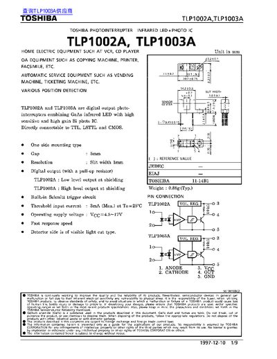
Toshiba TLP1002A/TLP1003A Datasheet
The TLP1002A and TLP1003A are digital‑output photo‑interrupters that combine a GaAs infrared LED with a high‑gain Si photo‑IC. They are designed for direct connection to TTL, LSTTL and CMOS logic and are used in home electric equipment, automatic service equipment, and various position‑detection applications.
The document lists maximum ratings, recommended operating conditions, opto‑electrical characteristics, and safety precautions. It also includes mechanical mounting guidance, such as the required shutter pitch relative to the device slit width, and detailed specifications for forward current, supply voltage, temperature range, and output characteristics.
Toshiba TLP1003A specifications
| Maximum Forward Current (I_F) | 50 mA |
|---|---|
| Reverse Voltage (V_R) | 5 V |
| Supply Voltage (V_CC) | 4.5 V – 17 V |
| Operating Temperature Range | -25 °C – 85 °C |
| Threshold Input Current | 3 mA (max) |
| Low Level Output Current | 16 mA (typ) |
| Device Weight | 0.88 g (typ) |
All Toshiba TLP1003A documents by type
Ratings, dimensions and ordering codes, for selection and design work.
Questions answered in these manuals
What is the maximum forward current for the TLP1002A/TLP1003A?
The maximum forward current is 50 mA.
What supply voltage range should be used with these sensors?
The devices operate with a supply voltage between 4.5 V and 17 V.
What is the output level of the TLP1002A?
The TLP1002A provides a low‑level digital output at shielding.
What supply voltage range is recommended for these devices?
The devices operate with a supply voltage between 4.5 V and 17 V.