
Key facts
- Brand
- Mitsubishi
- Model
- PS21963
- Category
- Other Electronics
- Industry
- Electronics
- Documents
- 8
- Languages
- EN
- Last added
- 2012-03-21
Start here
Mitsubishi PS21963-4E/4AE/4CE/4EW Intelligent Power Module Manual
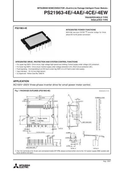
This manual describes the Mitsubishi PS21963 series Dual‑In‑Line Package Intelligent Power Module (DIP‑IPM). It integrates drive, protection, and system‑control functions for 600 V/8 A three‑phase inverter bridges used in small motor drives. The document includes package outlines, internal block diagrams, and recommended external circuitry.
Key information includes maximum voltage and current ratings, thermal resistance data, recommended wiring practices, and timing charts for short‑circuit and under‑voltage protection. The manual also details control‑supply voltages, fault‑output behavior, and mechanical mounting specifications.
Mitsubishi PS21963 specifications
| Inverter supply voltage (Veco) | 450 V |
|---|---|
| Collector‑emitter voltage (VCES) | 600 V |
| Continuous collector current per IGBT | 8 A |
| Collector dissipation per chip | 24.3 W |
| Isolation voltage | 1500 V |
| Fault‑output current (IFO) | 1 mA |
Source: Mitsubishi PS21963-4E/4AE/4CE/4EW Intelligent Power Module Manual
All Mitsubishi PS21963 documents by type
Day-to-day operation, settings and troubleshooting. Start here if the product is already set up.
- Mitsubishi PS21963-4E/4AE/4CE/4EW Intelligent Power Module Manual 10 p
- Mitsubishi PS21963-4ES Intelligent Power Module Manual 8 p
- MITSUBISHI PS21963-ET/-AET/-CET/-ET Manual 10 p
- MITSUBISHI PS21963-T/-AT/-CT/-TW Manual 10 p
- Mitsubishi PS21963-EST Intelligent Power Module Manual 8 p
- Mitsubishi PS21963-ST Intelligent Power Module Manual 8 p
Disassembly, diagnostics and part numbers, for repair.
Questions answered in these manuals
What is the maximum supply voltage for the inverter part?
The inverter supply voltage (Veco) is rated at 450 V applied between the P and N terminals.
From: Mitsubishi PS21963-4E/4AE/4CE/4EW Intelligent Power Module Manual
What wiring guidelines are recommended for the shunt resistor?
The shunt‑resistor wiring inductance should be less than 10 nH and the GND connection to the VNC terminal should be made as close as possible.
From: Mitsubishi PS21963-4E/4AE/4CE/4EW Intelligent Power Module Manual
What is the maximum collector‑emitter voltage rating of the PS21963-4ES?
The module is rated for a collector‑emitter voltage of 600 V.
From: Mitsubishi PS21963-4ES Intelligent Power Module Manual
What isolation voltage is provided between the pins and the heat‑sink plate?
The isolation voltage between pins and the heat‑sink plate is 1500 V.
From: Mitsubishi PS21963-4ES Intelligent Power Module Manual
What is the maximum continuous collector current for the PS21963-4S?
The module can continuously conduct 10 A per IGBT at 25 °C.
From: Mitsubishi PS21963-4S Intelligent Power Module Service Manual
How should the VNC terminals be connected?
Two VNC terminals (pins 9 & 16) are internally linked; connect either one to the 15 V power‑supply GND and leave the other open.