
Key facts
- Brand
- Mitsubishi
- Model
- RA30H4047M1
- Category
- MOS transistor
- Industry
- Electronics
- Documents
- 2
- Languages
- EN
- Last added
- 2012-03-21
Start here
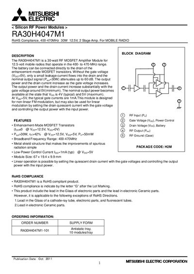
Mitsubishi Electric RA30H4047M1 RF Power Module Datasheet
The RA30H4047M1 is a 30‑watt RF MOSFET Amplifier Module designed for 12.5‑volt mobile radios operating in the 400‑470 MHz band. It features enhancement‑mode MOSFET transistors, a compact 67 × 19.4 × 9.9 mm package, low‑power control current (1 mA) and a metal shield that simplifies spurious radiation control.
The module requires careful mechanical handling, ESD protection, and proper thermal design. Recommended mounting uses M3 screws with a 4.0‑6.0 kgf‑cm torque, athermal compound between the module and heat sink, and a heat‑sink thermal resistance of about 0.67 °C/W to keep the case temperature below 90 °C. Soldering should be performed below 350 °C for less than 3 seconds, and only compatible fluxes may be used.
Mitsubishi RA30H4047M1 specifications
| Frequency Range | 400‑470 MHz |
|---|---|
| Output Power | 30 W |
| Gate Voltage (Vea) | <12.5 V |
| Input Power | 100 mW |
| Total Efficiency | 42 % |
| Package Size | 67 × 19.4 × 9.9 mm |
| Low‑Power Control Current | 1 mA (typ) |
| Operating Temperature Range | -30 °C to +100 °C |
| RoHS Compliance | Yes |
Source: Mitsubishi Electric RA30H4047M1 RF Power Module Datasheet
All Mitsubishi RA30H4047M1 documents by type
Ratings, dimensions and ordering codes, for selection and design work.
How to use the product for one specific task, with worked examples.
Questions answered in these manuals
What torque should be used for the mounting screws?
M3 screws are recommended with a tightening torque of 4.0 to 6.0 kgf‑cm.
From: Mitsubishi Electric RA30H4047M1 RF Power Module Datasheet
How should the leads be soldered to avoid damage?
Solder the leads after the module is screwed to the heat sink, keeping the solder temperature below 350 °C and the soldering time under 3 seconds.
From: Mitsubishi Electric RA30H4047M1 RF Power Module Datasheet
What type of semiconductor devices are RA30H4552M1 and RA30H4047M1?
Both devices are MOS FET silicon RF power semiconductors.
What are the electro‑static discharge test conditions used in the note?
The test used a 100 pF capacitor, 1.5 kΩ resistor, three discharges per voltage step, and increased the voltage up to 6000 V.