
The document introduces the PS21963-4E dual inline package intelligent power module's outline dimensions, characteristics, and functions. The module is suitable for small power motor control in three-phase DC-to-AC power conversion.
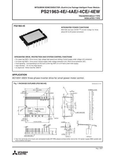
This manual describes the Mitsubishi PS21963 series Dual‑In‑Line Package Intelligent Power Module (DIP‑IPM). It integrates drive, protection, and system‑control functions for 600 V/8 A three‑phase inverter bridges used in small motor drives. The document includes package outlines, internal block diagrams, and recommended external circuitry.
Key information includes maximum voltage and current ratings, thermal resistance data, recommended wiring practices, and timing charts for short‑circuit and under‑voltage protection. The manual also details control‑supply voltages, fault‑output behavior, and mechanical mounting specifications.
| Inverter supply voltage (Veco) | 450 V |
|---|---|
| Collector‑emitter voltage (VCES) | 600 V |
| Continuous collector current per IGBT | 8 A |
| Collector dissipation per chip | 24.3 W |
| Isolation voltage | 1500 V |
| Fault‑output current (IFO) | 1 mA |
The inverter supply voltage (Veco) is rated at 450 V applied between the P and N terminals.
The shunt‑resistor wiring inductance should be less than 10 nH and the GND connection to the VNC terminal should be made as close as possible.