
Key facts
- Brand
- Mitsubishi
- Model
- PS21265-P
- Documents
- 3
- Languages
- EN
- Last added
- 2012-03-21
Start here
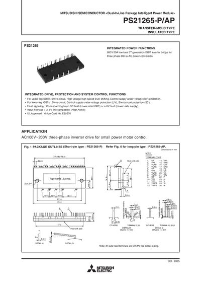
Mitsubishi PS21265-P/AP Intelligent Power Module User Manual
The Mitsubishi PS21265-P/AP is a dual‑in‑line package intelligent power module (IPM) designed for three‑phase inverter drives up to 600 V and 20 A. The manual provides integrated drive, protection and system control functions, including fault signaling, under‑voltage and short‑circuit protection.
The document includes maximum electrical ratings, thermal resistance data, mechanical characteristics, recommended operating conditions, timing charts for protective functions, wiring guidelines, and example application circuits to help engineers integrate the module safely and efficiently.
Mitsubishi PS21265-P specifications
| Supply voltage (Veco) | 450 V |
|---|---|
| Collector‑emitter voltage (VCES) | 600 V |
| Collector current per IGBT | 20 A |
| Collector dissipation per chip | 51.2 W |
| Control supply voltage (VD) | 20 V |
| Isolation voltage | 2500 V rms (1 min, 60 Hz) |
| Weight | 54 g |
| Recommended mounting torque | 1.18 N·m |
Source: Mitsubishi PS21265-P/AP Intelligent Power Module User Manual
All Mitsubishi PS21265-P documents by type
Day-to-day operation, settings and troubleshooting. Start here if the product is already set up.
Questions answered in these manuals
What is the maximum collector current for each IGBT?
Each IGBT can carry up to 20 A continuous collector current.
From: Mitsubishi PS21265-P/AP Intelligent Power Module User Manual
What mounting torque is recommended for the module screws?
A torque of 1.18 N·m is recommended for the M4 mounting screw.
From: Mitsubishi PS21265-P/AP Intelligent Power Module User Manual
What is the maximum collector‑emitter voltage rating?
The IPM is rated for a collector‑emitter voltage of 600 V.
From: MITSUBISHI SEMICONDUCTORMITSUBISHI SEMICONDUCTOR PS21265-P/AP Manual
How should the VNC (ground) connections be made?
Two VNC terminals (pins 9 & 16) are internally connected; connect either one to the 15 V power‑supply ground and leave the other open.
From: MITSUBISHI SEMICONDUCTORMITSUBISHI SEMICONDUCTOR PS21265-P/AP Manual