
Key facts
- Brand
- Mitsubishi
- Model
- MGF0951P
- Documents
- 5
- Languages
- EN
- Last added
- 2012-03-21
Start here
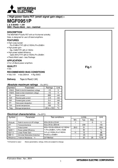
Mitsubishi Electric MGF0951P GaAs FET Datasheet
The MGF0951P is a high‑power GaAs field‑effect transistor designed for L/S‑band power amplifiers. It features an N‑channel Schottky gate and is supplied in an SMD plastic‑mold, non‑matched package.
Key specifications include a typical output power of 31 dBm at 2.15 GHz with 20 dBm input, a gain of 13 dB, and a power‑added efficiency of about 50 %. The device can handle a drain current of 800 mA and a total power dissipation of 6 W, with recommended bias conditions of Vds = 10 V, Ids = 200 mA, and a gate resistor of 500 Ω. Safety and handling notes are provided at the end of the document.
Mitsubishi MGF0951P specifications
| Typical output power (Po) | 31 dBm |
|---|---|
| Typical gain (Gp) | 13 dB |
| Power‑added efficiency (nadd) | 50 % |
| Gate‑to‑source breakdown voltage (VGS0) | -15 V |
| Drain current (ID) | 800 mA |
| Total power dissipation (PT) | 6.0 W |
| Storage temperature range | -40 to +150 °C |
| Package type | SMD / Plastic Mold non‑matched |
| Recommended bias conditions | Vds=10 V, Ids=200 mA, Rg=500 Ω |
All Mitsubishi MGF0951P documents by type
Ratings, dimensions and ordering codes, for selection and design work.
How to use the product for one specific task, with worked examples.
Questions answered in these manuals
What is the typical output power of the MGF0951P?
The typical output power is 31 dBm at 2.15 GHz with a 20 dBm input.
What gain does the MGF0951P provide?
It provides a typical gain of 13 dB at 2.15 GHz.
What supply voltage was used during the RF measurements?
The measurements were performed with a supply voltage of 10 V.
Which frequency range does the data cover?
The RF test data cover the 2.5 GHz to 2.7 GHz band.
What supply voltage was used during the RF measurements?
A supply voltage of 10 V (VD) was applied.
What bias current (IDQ) was set for the tests?
The bias current was set to 0.2 A.