
This application note shows the RF characteristics data of MGF0951P, including evaluation conditions and results, in the frequency range of 2.3-2.4GHz.
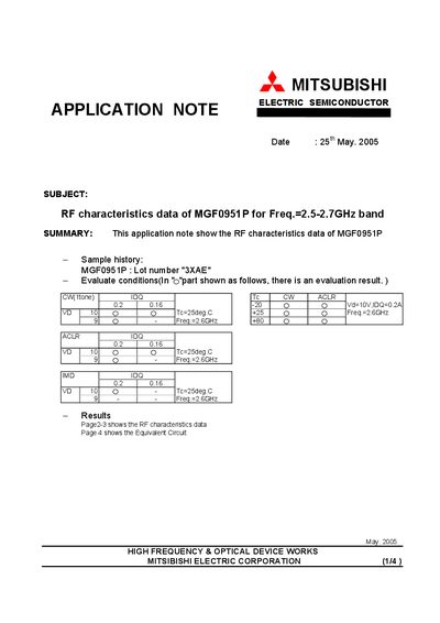
The document presents measured RF performance of the MGF0951P device, including power‑output versus input power, ACLR, IMD and other key parameters. Test conditions such as a 10 V supply (VD) and 0.2 A bias current (IDQ) at 25 °C are described.
Additional sections show the equivalent circuit, component values for the test fixture, and board material specifications. The data are organized in tables and graphs for frequencies from 2.5 GHz to 2.7 GHz.
| Supply voltage (VD) | 10 V |
|---|---|
| Bias current (IDQ) | 0.2 A |
| Frequency range | 2.5‑2.7 GHz |
| Test temperature | 25 °C |
| C1‑C4 capacitance | 708 × 20 pF |
| C5‑C7‑C8 capacitance | 1000 pF |
| C9‑G10 capacitance | 1 pF |
| Electrolytic capacitor | 47 µF |
| Inductor L1‑L2 | 12 nH |
| Resistor R1 | 51 Ω |
| Resistor R2 | 500 Ω |
| Board material thickness | 0.8 mm |
| Dielectric constant of board | 4.4 |
A supply voltage of 10 V (VD) was applied.
The bias current was set to 0.2 A.
The data cover the 2.5 GHz to 2.7 GHz band.
The board thickness is 0.8 mm.