
This application note shows the RF characteristics data of MGF0951P
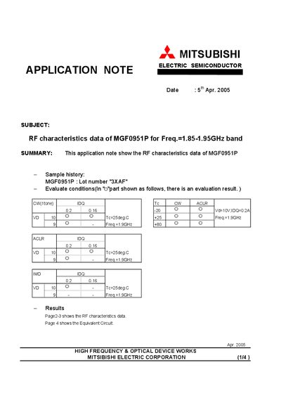
The document presents measured RF characteristics of the MGF0951P device, including output power versus input power, ACLR, and IM3/IM5 results under defined test conditions (VD=10 V, IDQ=0.2‑0.5 A, Tc=25 °C, frequency 1.9 GHz). Sample history and lot number are also listed.
Pages 2‑3 contain the full set of RF performance graphs, while page 4 describes the test fixture used for the measurements, specifying component values such as capacitors, resistors, and inductors, and provides the equivalent circuit model.
| Supply voltage (VD) | 10 V |
|---|---|
| Quiescent current (IDQ) | 0.5 A |
| Test temperature (Tc) | 25 °C |
| Test frequency | 1.9 GHz |
| Capacitor C1‑C4 | 20 pF |
| Capacitor C5‑C8 | 1000 pF |
| Capacitor C10 | 1 pF |
| Capacitor C11 | 3 pF |
| Resistor R1 | 510 Ω |
| Resistor R2 | 500 Ω |
| Inductor L2 | 12 nH |
| Dielectric constant of substrate | 4.4 |
The measurements were performed with a supply voltage of 10 V.
The data cover the 1.85‑1.95 GHz band, with key plots shown at 1.9 GHz.
The sample belongs to lot number 3XAF.