
Key facts
- Brand
- Analog Devices
- Model
- ADP3605
- Industry
- Industrial
- Documents
- 2
- Languages
- EN
- Last added
- 2012-05-05
Start here
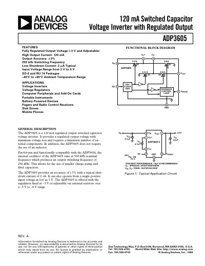
Analog Devices ADP3605 Switched Capacitor Voltage Inverter Datasheet
The ADP3605 provides a regulated negative output voltage from a positive input without an inductor, using a switched‑capacitor charge‑pump architecture. It operates from 3 V to 6 V supply, delivers up to 120 mA output current, and features a typical shutdown current of 2 mA.
The device is offered in SO‑8 and RU‑14 packages, supports a 250 kHz switching frequency, and includes ESD protection. Detailed specifications, layout guidelines, and capacitor selection advice are provided for optimal performance.
Analog Devices ADP3605 specifications
| Operating Supply Voltage Range | 3 V – 6 V |
|---|---|
| Maximum Output Current | 120 mA |
| Typical Switching Frequency | 250 kHz |
| Shutdown Mode Current | 2 mA (typical) |
| Output Resistance (Open Loop) | 9 Ω |
| Power Dissipation (SO‑8) | 660 mW |
Source: Analog Devices ADP3605 Switched Capacitor Voltage Inverter Datasheet
All Analog Devices ADP3605 documents by type
Ratings, dimensions and ordering codes, for selection and design work.
Questions answered in these manuals
What is the typical switching frequency of the ADP3605?
The ADP3605 operates at a typical switching frequency of 250 kHz.
From: Analog Devices ADP3605 Switched Capacitor Voltage Inverter Datasheet
What is the shutdown current when the device is in shutdown mode?
In shutdown mode the device draws about 2 mA of current.
From: Analog Devices ADP3605 Switched Capacitor Voltage Inverter Datasheet
What is the typical shutdown current of the ADP3605?
The device has a typical shutdown current of 2 A.
How can the output be disabled?
Pull the SD pin (Pin 4) high to a TTL/CMOS logic level to disable the output.