
This document is the application manual of ADP3605, which introduces the basic functions and characteristics of ADP3605, application scenarios, package forms, working temperature range and other information.
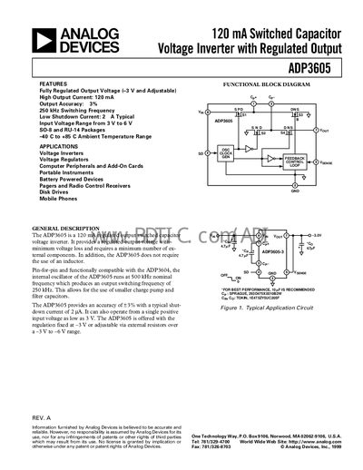
The ADP3605 is a 120 mA regulated‑output switched‑capacitor voltage inverter that provides a negative output without an external inductor. It operates from a single positive input voltage as low as 3 V and offers a fully regulated output of –3 V (fixed) or an adjustable range of –3 V to –6 V.
The document includes functional block diagrams, pin descriptions, recommended capacitor technologies, and design guidelines such as layout practices, shutdown operation, and power‑dissipation calculations. It also provides ordering information for SO‑8 and TSSOP (RU‑14) packages.
| Operating Supply Voltage Range | 3 V to 6 V |
|---|---|
| Maximum Output Current | 120 mA |
| Switching Frequency | 250 kHz |
| Typical Shutdown Current | 2 A (typical) |
The device has a typical shutdown current of 2 A.
Pull the SD pin (Pin 4) high to a TTL/CMOS logic level to disable the output.
Solid tantalum and multilayer ceramic capacitors are recommended for low ESR.
The internal switches operate at a nominal frequency of 250 kHz.