
Key facts
- Brand
- Analog Devices
- Model
- AD5114
- Category
- Other Electronics
- Documents
- 2
- Languages
- EN
- Last added
- 2012-08-02
Start here
ANALOG DEVICES UG-378 handbook
Quick Start Guide 4 pages · 149 KB · EN
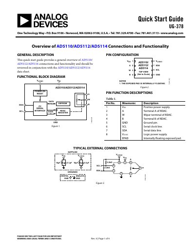
The document describes the AD5110/AD5112/AD5114 digital potentiometers, including the functional block diagram, pin configuration, pin function descriptions, and typical external connections. It covers operational conditions, I2C command set, shift register timing, and examples for calculating end-to-end resistance and writing/reading registers.
Read onlineAnalog Devices AD5114 specifications
| VDD supply voltage | 2.3 V to 5.5 V |
|---|---|
| VLOGIC supply voltage | 1.8 V to VDD |
| Maximum continuous current (5 kΩ, 10 kΩ) | ±6 mA |
| Maximum continuous current (80 kΩ) | ±1.5 mA |
| Maximum I2C clock frequency | 400 kHz |
Source: ANALOG DEVICES UG-378 handbook
All Analog Devices AD5114 documents by type
Quick Start Guide 1
The shortest path to a working setup, usually only a few pages.
Other documents 1
Questions answered in these manuals
What is the operating voltage range for VDD?
The VDD supply voltage ranges from 2.3 V to 5.5 V.
How do you calculate the actual end-to-end resistance?
Read the resistor tolerance data from EEPROM, compute the tolerance percentage, and apply it to the nominal resistance; for example, a tolerance of -10.25% on a 10 kΩ resistor gives 8.975 kΩ.