
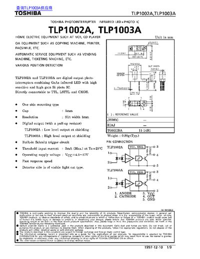
The TLP1002A and TLP1003A are digital‑output photo‑interrupters that combine a GaAs infrared LED with a high‑gain Si photo‑IC. They are designed for direct connection to TTL, LSTTL and CMOS logic and are used in home electric equipment, automatic service equipment, and various position‑detection applications.
The document lists maximum ratings, recommended operating conditions, opto‑electrical characteristics, and safety precautions. It also includes mechanical mounting guidance, such as the required shutter pitch relative to the device slit width, and detailed specifications for forward current, supply voltage, temperature range, and output characteristics.
| Maximum Forward Current (I_F) | 50 mA |
|---|---|
| Reverse Voltage (V_R) | 5 V |
| Supply Voltage (V_CC) | 4.5 V – 17 V |
| Operating Temperature Range | -25 °C – 85 °C |
| Threshold Input Current | 3 mA (max) |
| Low Level Output Current | 16 mA (typ) |
| Device Weight | 0.88 g (typ) |
The maximum forward current is 50 mA.
The devices operate with a supply voltage between 4.5 V and 17 V.
Soldering should be performed after lead forming, and only limited chemicals should be used for cleaning to avoid damaging the polycarbonate package.