
This document presents the electrostatic discharge test results for RA30H4552M1 and RA30H4047M1. It explains that these two products use MOS FET devices, which have lower surge endurance compared to silicon bipolar devices and may burn out when exposed to static electricity or surges.
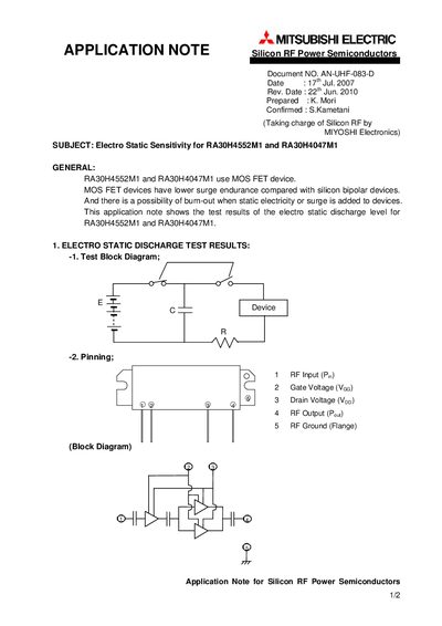
The document provides an overview of electro‑static sensitivity for the RA30H4552M1 and RA30H4047M1 MOS FET RF power devices. It explains that MOS FETs have lower surge endurance than silicon bipolar devices and can be damaged by static discharge.
Test procedures include a block diagram, pin assignments, and human model test results. Test conditions were C=100 pF, R=1.5 kΩ, three discharges per voltage step, with voltage increased up to 6000 V. The results show the voltage levels at which the devices were destroyed for various pin‑to‑ground polarities.
| Device type | MOS FET |
|---|---|
| Power rating (RA30H4047M1) | >30 W @400‑470 MHz |
| Supply voltage (RA30H4047M1) | 12.5 V |
| Test capacitance | 100 pF |
| Maximum discharge voltage before failure | up to 6000 V |
Both devices are MOS FET silicon RF power semiconductors.
The test used a 100 pF capacitor, 1.5 kΩ resistor, three discharges per voltage step, and increased the voltage up to 6000 V.
The RA30H4047M1 is rated for more than 30 W at 400‑470 MHz with a supply voltage of 12.5 V.
Failure occurred at 1400 V for the first sample and at 2700 V for the second sample when the pin was positive to the flange.