
The PS21962-4 is a 600V/5A low-loss fifth-generation IGBT inverter bridge for three-phase DC-to-AC power conversion, which is suitable for small power motor control AC100V~200V three-phase inverter drive.
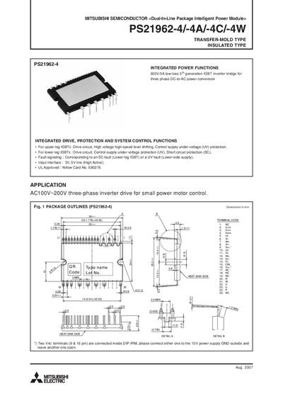
The PS21962-4 series is a dual‑in‑line package intelligent power module (IPM) that integrates IGBTs, driver circuits, and protection functions for three‑phase inverter applications such as small‑power motor control. It offers 600 V/5 A low‑loss operation and includes built‑in short‑circuit and under‑voltage protection.
The document details package dimensions, internal block diagrams, external protection circuitry, maximum ratings, electrical and mechanical characteristics, recommended operating conditions, timing charts for protective functions, wiring recommendations, and example application circuits. It also provides guidance on component selection, thermal management, and interface connections for MCU integration.
| Supply voltage (P‑N) | 450 V |
|---|---|
| Surge supply voltage (P‑N) | 500 V |
| Collector‑emitter voltage (VCES) | 600 V |
| Continuous collector current (per IGBT) | 5 A |
| Power dissipation per chip | 21.3 W |
| Junction temperature range | −20 °C to +125 °C |
| Control supply voltage (Vb) | 13.5 V – 16.5 V |
| Control supply voltage (VDB) | 13.0 V – 18.5 V |
| Isolation voltage (pin to heat‑sink) | 1500 V |
The IPM is rated for a collector‑emitter voltage of 600 V.
Two VNC terminals (pins 9 & 16) are internally connected; connect either one to the 15 V power‑supply ground and leave the other open.